Capacitors
A capacitor can be made physically using two parallel conducting
plates which are held close together (but not touching). Electric
charge can be stored in a capacitor by applying a voltage across the
plates.
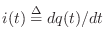
The defining equation of a capacitor  is
is
 |
(E.2) |
where

denotes the capacitor's
charge in
Coulombs,
is the
capacitance in
Farads, and

is the
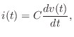
voltage drop across the capacitor in volts. Differentiating with
respect to time gives
where
is now the
current in
Amperes. Note that, by convention, the current is taken to be
positive when flowing from plus to minus across the capacitor (see the
arrow in Fig.
E.1 which indicates the direction of current
flow--there is only one current

flowing clockwise around the
loop formed by the voltage source, resistor, and capacitor when an
external voltage

is applied).
Taking the Laplace transform of both sides gives
by the
differentiation theorem for Laplace transforms (§
D.4.2).
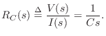
Assuming a zero initial voltage across the capacitor at time 0, we have
We call this the
driving-point impedance of the capacitor. The
driving-point
impedance facilitates
steady state analysis (zero
initial conditions) by allowing the capacitor to be analyzed like a
simple resistor, with value
 Ohms
Ohms.
Mechanical Equivalent of a Capacitor is a Spring
The mechanical analog of a capacitor is the compliance of a
spring. The voltage across a capacitor corresponds to the
force  used to displace a spring. The charge stored in
the capacitor corresponds to the displacement
used to displace a spring. The charge stored in
the capacitor corresponds to the displacement  of the spring.
Thus, Eq.
of the spring.
Thus, Eq. (E.2) corresponds to Hooke's law for ideal springs:
where

is called the
spring constant or
spring stiffness.
Note that
Hooke's law is usually written as

. The quantity

is called the
spring compliance.
Next Section: InductorsPrevious Section: Example Analog Filter