


Peaking Equalizers
A peaking equalizer filter section provides a boost or cut in the vicinity of some center frequency. It may also be called a parametric equalizer section. The gain far away from the boost or cut is unity, so it is convenient to combine a number of such sections in series. Additionally, a high and/or low shelf (§B.4 above) are nice to include in series with one's peaking eq sections.
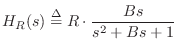
The analog transfer function for a peak filter is given by [103,5,6]
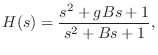
It is easy to show that both zeros and both poles are on the unit
circle in the left-half ![]() plane, and when
plane, and when ![]() (a ``cut''), the
zeros are closer to the
(a ``cut''), the
zeros are closer to the ![]() axis than the poles.
axis than the poles.
Again, the bilinear transform can be used to convert the analog peaking equalizer section to digital form.
Figure B.15 gives a matlab listing for a peaking EQ section. Figure B.16 shows the resulting plot for an example call:
boost(2,0.25,0.1);The frequency-response utility myfreqz, listed in Fig.7.1, can be substituted for freqz.
function [B,A] = boost(gain,fc,bw,fs); %BOOST - Design a boost filter at given gain, center % frequency fc, bandwidth bw, and sampling rate fs % (default = 1). % % J.O. Smith 11/28/02 % Reference: Zolzer: Digital Audio Signal Processing, p. 124 if nargin<4, fs = 1; end if nargin<3, bw = fs/10; end Q = fs/bw; wcT = 2*pi*fc/fs; K=tan(wcT/2); V=gain; b0 = 1 + V*K/Q + K^2; b1 = 2*(K^2 - 1); b2 = 1 - V*K/Q + K^2; a0 = 1 + K/Q + K^2; a1 = 2*(K^2 - 1); a2 = 1 - K/Q + K^2; A = [a0 a1 a2] / a0; B = [b0 b1 b2] / a0; if nargout==0 figure(1); freqz(B,A); title('Boost Frequency Response') end |
![\includegraphics[width=\twidth]{eps/tboost}](http://www.dsprelated.com/josimages_new/filters/img1489.png) |
A Faust implementation of the peaking equalizer is available as the function peak_eq in filter.lib distributed with Faust (Appendix K) starting with version 0.9.9.4k-par.
Next Section:
Time-Varying Two-Pole Filters
Previous Section:
Low and High Shelving Filters


