Sign in

username:

password:


Not a member?

Search Online Books


Search tips

Free Online Books

Sponsor

DM6467T DaVinci video processor enables H.264 1080p decoding up to 60 fps/eight D1 channel encoding.
Details Here!

Chapters

See Also

Embedded SystemsFPGAElectronics

Chapter Contents:

Search Introduction to Digital Filters


Book Index | Global Index


Would you like to be notified by email when Julius Orion Smith III publishes a new entry into his blog?


Transposed Direct-Forms

The remaining two direct forms are obtained by formally transposing direct-forms I and II [60, p. 155]. Filter transposition may also be called flow graph reversal, and transposing a Single-Input, Single-Output (SISO) filter does not alter its transfer function. This fact can be derived as a consequence of Mason's gain formula for signal flow graphs [49,50] or Tellegen's theorem (which implies that an LTI signal flow graph is interreciprocal with its transpose) [60, pp. 176-177]. Transposition of filters in state-space form is discussed in §G.5.

The transpose of a SISO digital filter is quite straightforward to find: Reverse the direction of all signal paths, and make obviously necessary accommodations. ``Obviously necessary accommodations'' include changing signal branch-points to summers, and summers to branch-points. Also, after this operation, the input signal, normally drawn on the left of the signal flow graph, will be on the right, and the output on the left. To renormalize the layout, the whole diagram is usually left-right flipped.

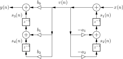
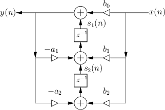
Figure 9.3 shows the Transposed-Direct-Form-I (TDF-I) structure for the general second-order IIR digital filter, and Fig.9.4 shows the Transposed-Direct-Form-II (TDF-II) structure. To facilitate comparison of the transposed with the original, the inputs and output signals remain ``switched'', so that signals generally flow right-to-left instead of the usual left-to-right. (Exercise: Derive forms TDF-I/II by transposing the DF-I/II structures shown in Figures 9.1 and 9.2.)

Figure: Transposed-Direct-Form-I implementation of a second-order IIR digital filter. Note that the input signal comes in from the right, and the output is on the left. Compare to Fig.9.1. The four ``state variable'' signals are labeled arbitrarily as $ s_1(n)$ through $ s_4(n)$.
\begin{figure}\input fig/tdfi.pstex_t
\end{figure}

Figure: Transposed-Direct-Form-II implementation of a second-order IIR digital filter (input on the right, output on the left). Compare to Fig.9.2.
\begin{figure}\input fig/tdfii.pstex_t
\end{figure}


Order a Hardcopy of Introduction to Digital Filters

Previous: More about Potential Internal Overflow of DF-II
Next: Numerical Robustness of TDF-II

written by Julius Orion Smith III
Julius Smith's background is in electrical engineering (BS Rice 1975, PhD Stanford 1983). He is presently Professor of Music and Associate Professor (by courtesy) of Electrical Engineering at Stanford's Center for Computer Research in Music and Acoustics (CCRMA), teaching courses and pursuing research related to signal processing applied to music and audio systems. See http://ccrma.stanford.edu/~jos/ for details.


Comments


No comments yet for this page


Add a Comment
You need to login before you can post a comment (best way to prevent spam). ( Not a member? )