


Allpass from Two Combs
An allpass filter can be defined as any filter having a gain of
![]() at all frequencies (but typically different delays at different
frequencies).
at all frequencies (but typically different delays at different
frequencies).
It is well known that the series combination of a feedforward and feedback comb filter (having equal delays) creates an allpass filter when the feedforward coefficient is the negative of the feedback coefficient.
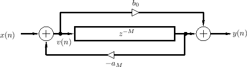
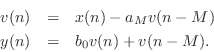
Figure 2.30 shows a combination feedforward/feedback comb filter structure which shares the same delay line.3.13 By inspection of Fig.2.30, the difference equation is
This can be recognized as a digital filter in direct form II
[449]. Thus, the system of Fig.2.30 can be interpreted as
the series combination of a feedback comb filter (Fig.2.24) taking
![]() to
to ![]() followed by a feedforward comb filter (Fig.2.23)
taking
followed by a feedforward comb filter (Fig.2.23)
taking ![]() to
to ![]() . By the commutativity of LTI systems, we can
interchange the order to get
. By the commutativity of LTI systems, we can
interchange the order to get
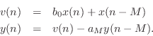
Substituting the right-hand side of the first equation above for
![]() in the second equation yields more simply
in the second equation yields more simply
This can be recognized as direct form I [449], which requires
The coefficient symbols ![]() and
and ![]() here have been chosen to
correspond to standard notation for the transfer function
here have been chosen to
correspond to standard notation for the transfer function

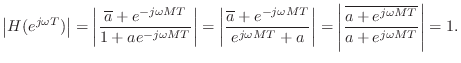
An allpass filter is obtained when
![]() , or, in the case
of real coefficients, when
, or, in the case
of real coefficients, when ![]() . To see this, let
. To see this, let
![]() . Then we have
. Then we have
Next Section:
Nested Allpass Filters
Previous Section:
FDN Stability


