


Classic Analog Phase Shifters
Setting ![]() in Eq.
in Eq.![]() (8.19) gives the frequency response
of the analog-phaser transfer function to be
(8.19) gives the frequency response
of the analog-phaser transfer function to be
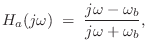
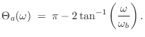
Figure 8.24a shows the phase responses of four first-order analog
allpass filters with ![]() set to
set to
![]() .
Figure 8.24b shows the resulting normalized amplitude response for
the phaser, for
.
Figure 8.24b shows the resulting normalized amplitude response for
the phaser, for ![]() (unity feedfoward gain). The amplitude response
has also been normalized by dividing by 2 so that the maximum gain is
1. Since there is an even number (four) of allpass sections, the gain
at dc is
(unity feedfoward gain). The amplitude response
has also been normalized by dividing by 2 so that the maximum gain is
1. Since there is an even number (four) of allpass sections, the gain
at dc is
![]() . Put another way, the initial
phase of each allpass section at dc is
. Put another way, the initial
phase of each allpass section at dc is ![]() , so that the total
allpass-chain phase at dc is
, so that the total
allpass-chain phase at dc is ![]() . As frequency increases, the
phase of the allpass chain decreases. When it comes down to
. As frequency increases, the
phase of the allpass chain decreases. When it comes down to ![]() ,
the net effect is a sign inversion by the allpass chain, and the
phaser has a notch. There will be another notch when the phase falls
down to
,
the net effect is a sign inversion by the allpass chain, and the
phaser has a notch. There will be another notch when the phase falls
down to ![]() . Thus, four first-order allpass sections give two
notches. For each notch in the desired response we must add two new
first-order allpass sections.
. Thus, four first-order allpass sections give two
notches. For each notch in the desired response we must add two new
first-order allpass sections.
![\includegraphics[width=\twidth]{eps/phaser1a}](http://www.dsprelated.com/josimages_new/pasp/img1910.png) |
From Fig.8.24b, we observe that the first notch is near ![]() Hz. This happens to be the frequency at which the first allpass pole
``breaks,'' i.e.,
Hz. This happens to be the frequency at which the first allpass pole
``breaks,'' i.e.,
![]() . Since the phase of a first-order
allpass section at its break frequency is
. Since the phase of a first-order
allpass section at its break frequency is ![]() , the sum of the
other three sections must be approximately
, the sum of the
other three sections must be approximately
![]() .
Equivalently, since the first section has ``given up''
.
Equivalently, since the first section has ``given up'' ![]() radians
of phase at
radians
of phase at
![]() , the other three allpass sections
combined have given up
, the other three allpass sections
combined have given up ![]() radians as well (with the second
section having given up more than the other two).
radians as well (with the second
section having given up more than the other two).
In practical operation, the break frequencies must change dynamically, usually periodically at some rate.
Next Section:
Classic Virtual Analog Phase Shifters
Previous Section:
Matlab Code for Inverse Filtering


