


Conventional Ladder Filters
Given a reflecting termination on the right, the half-rate DWF chain of Fig.C.25 can be reduced further to the conventional ladder/lattice filter structure shown in Fig.C.26.
To make a standard ladder/lattice filter, the sampling rate is cut in
half (i.e., replace ![]() by
by ![]() ), and the scattering junctions are
typically implemented in one-multiply form (§C.8.5) or
normalized form (§C.8.6), etc. Conventionally, if the
graph of the scattering junction is nonplanar, as it is for the
one-multiply junction, the filter is called a lattice filter;
it is called a ladder filter when the graph is planar, as it is
for normalized and Kelly-Lochbaum scattering junctions. For all-pole
transfer functions
), and the scattering junctions are
typically implemented in one-multiply form (§C.8.5) or
normalized form (§C.8.6), etc. Conventionally, if the
graph of the scattering junction is nonplanar, as it is for the
one-multiply junction, the filter is called a lattice filter;
it is called a ladder filter when the graph is planar, as it is
for normalized and Kelly-Lochbaum scattering junctions. For all-pole
transfer functions
![]() , the Durbin
recursion can be used to compute the reflection coefficients
, the Durbin
recursion can be used to compute the reflection coefficients ![]() from the desired transfer-function denominator polynomial coefficients
[449]. To implement arbitrary transfer-function zeros, a
linear combination of delay-element outputs is formed using weights
that are called ``tap parameters'' [173,297].
from the desired transfer-function denominator polynomial coefficients
[449]. To implement arbitrary transfer-function zeros, a
linear combination of delay-element outputs is formed using weights
that are called ``tap parameters'' [173,297].
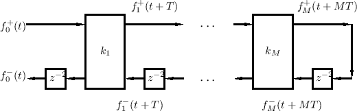
To create Fig.C.26 from Fig.C.24, all delays along the top rail
are pushed to the right until they have all been worked around to the
bottom rail. In the end, each bottom-rail delay becomes ![]() seconds
instead of
seconds
instead of ![]() seconds. Such an operation is possible because of the
termination at the right by an infinite (or zero) wave impedance.
Note that there is a progressive one-sample time advance from section
to section. The time skews for the right-going (or left-going)
traveling waves can be determined simply by considering how many
missing (or extra) delays there are between that signal and the
unshifted signals at the far left.
seconds. Such an operation is possible because of the
termination at the right by an infinite (or zero) wave impedance.
Note that there is a progressive one-sample time advance from section
to section. The time skews for the right-going (or left-going)
traveling waves can be determined simply by considering how many
missing (or extra) delays there are between that signal and the
unshifted signals at the far left.
Due to the reflecting termination, conventional lattice filters cannot
be extended to the right in any physically meaningful way. Also,
creating network topologies more complex than a simple linear cascade
(or acyclic tree) of waveguide sections is not immediately possible
because of the delay-free path along the top rail. In particular, the
output ![]() cannot be fed back to the input
cannot be fed back to the input ![]() . Nevertheless,
as we have derived, there is an exact physical interpretation (with
time skew) for the conventional ladder/lattice digital filter.
. Nevertheless,
as we have derived, there is an exact physical interpretation (with
time skew) for the conventional ladder/lattice digital filter.
Next Section:
Power-Normalized Waveguide Filters
Previous Section:
Half-Rate Ladder Waveguide Filters


