


Ideal Acoustic Tube
As discussed in §C.7.3, the most commonly used digital waveguide variables (``wave variables'') for acoustic tube simulation are traveling pressure and volume-velocity samples. These variables are exactly analogous to the traveling force and transverse-velocity waves used for vibrating string models.
The Ohm's law relations for acoustic-tube wave variables may be
written as follows (cf. Eq.![]() (6.6)):
(6.6)):
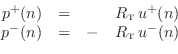
Here
| (7.8) |
where
In this formulation, the acoustic tube is assumed to contain only
traveling plane waves to the left and right. This is a
reasonable assumption for wavelengths ![]() much larger than the
tube diameter (
much larger than the
tube diameter (
![]() ). In this case, a change in the
tube cross-sectional area
). In this case, a change in the
tube cross-sectional area ![]() along the tube axis will cause lossless
scattering of incident plane waves. That is, the plane wave
splits into a transmitted and reflected component such that wave
energy is conserved (see Appendix C for a detailed derivation).
along the tube axis will cause lossless
scattering of incident plane waves. That is, the plane wave
splits into a transmitted and reflected component such that wave
energy is conserved (see Appendix C for a detailed derivation).
![\includegraphics[width=\twidth]{eps/KellyLochbaum}](http://www.dsprelated.com/josimages_new/pasp/img1343.png) |
Figure 6.2 shows a piecewise cylindrical tube model of the
vocal tract and a corresponding digital simulation [245,297].
In the figure, ![]() denotes the reflection coefficient
associated with the first tube junction (where the cross-sectional
area changes), and
denotes the reflection coefficient
associated with the first tube junction (where the cross-sectional
area changes), and ![]() is the corresponding transmission
coefficient for traveling pressure plane waves. The
corresponding reflection and transmission coefficients for
volume velocity are
is the corresponding transmission
coefficient for traveling pressure plane waves. The
corresponding reflection and transmission coefficients for
volume velocity are ![]() and
and ![]() , respectively. Again,
see Appendix C for a complete derivation.
, respectively. Again,
see Appendix C for a complete derivation.
At higher frequencies, those for which
![]() , changes
in the tube cross-sectional area
, changes
in the tube cross-sectional area ![]() give rise to mode
conversion (which we will neglect in this chapter).
Mode conversion means that an incident plane wave (the simplest mode of
propagation in the tube) generally
scatters into waves traveling in many directions, not just the two
directions along the tube axis. Furthermore, even along the tube axis,
there are higher orders of mode propagation associated with ``node lines''
in the transverse plane (such as Bessel functions of integer order
[541]). When mode conversion occurs, it is necessary to keep
track of many components in a more general modal expansion of
the acoustic field [336,13,50]. We may say that
when a plane wave encounters a change in the cross-sectional tube
area, it is ``converted'' into a sum of propagation modes. The coefficients
(amplitude and phase) of the new modes are typically found by matching
boundary conditions. (Pressure and volume-velocity must be continuous
throughout the tube.)
give rise to mode
conversion (which we will neglect in this chapter).
Mode conversion means that an incident plane wave (the simplest mode of
propagation in the tube) generally
scatters into waves traveling in many directions, not just the two
directions along the tube axis. Furthermore, even along the tube axis,
there are higher orders of mode propagation associated with ``node lines''
in the transverse plane (such as Bessel functions of integer order
[541]). When mode conversion occurs, it is necessary to keep
track of many components in a more general modal expansion of
the acoustic field [336,13,50]. We may say that
when a plane wave encounters a change in the cross-sectional tube
area, it is ``converted'' into a sum of propagation modes. The coefficients
(amplitude and phase) of the new modes are typically found by matching
boundary conditions. (Pressure and volume-velocity must be continuous
throughout the tube.)
As mentioned above, in acoustic tubes we work with volume
velocity, because it is volume velocity that is conserved when a
wave propagates from one tube section to another. For plane waves in
open air, on the other hand, we use particle velocity, and in
this case, the wave impedance of open air is
![]() instead.
That is, the appropriate wave impedance in open air (not inside an
acoustic tube) is pressure divided by particle-velocity for any traveling
plane wave. If
instead.
That is, the appropriate wave impedance in open air (not inside an
acoustic tube) is pressure divided by particle-velocity for any traveling
plane wave. If ![]() denotes a sample of the volume-velocity
plane-wave traveling to the right in an acoustic tube of
cross-sectional area
denotes a sample of the volume-velocity
plane-wave traveling to the right in an acoustic tube of
cross-sectional area ![]() , and if
, and if ![]() denotes the corresponding
particle velocity, then we have
denotes the corresponding
particle velocity, then we have
Next Section:
Rigid Terminations
Previous Section:
Ideal Vibrating String


