Sign in

username:

password:


Not a member?

Search Online Books


Search tips

Free Online Books

Ads

Chapters

See Also

Embedded SystemsFPGAElectronics
Chapter Contents:

Search Physical Audio Signal Processing


Book Index | Global Index


Would you like to be notified by email when Julius Orion Smith III publishes a new entry into his blog?


Parallel Combination of One-Ports

Figure Fig.L.10 shows the parallel combination of two one-ports.

Figure L.10: Two one-port networks combined in parallel. The admittance of the parallel combination is $ \Gamma (s) = \Gamma _1(s) + \Gamma _2(s)$.
\includegraphics[scale=0.9]{eps/lparallel}

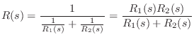
Admittances add in parallel, so the combined admittance is $ \Gamma (s) = \Gamma _1(s) + \Gamma _2(s)$, and the impedance is

$\displaystyle R(s) = \frac{1}{\frac{1}{R_1(s)} + \frac{1}{R_2(s)}}
= \frac{R_1(s) R_2(s) }{R_1(s) + R_2(s)}
$

which is the familiar product-over-sum rule for combining impedances in parallel. This operation is often denoted by

$\displaystyle R= R_1 \vert\vert R_2
$

When two physical elements are driven by a common force (yet have independent velocities, as we'll soon see is quite possible), they are formally in parallel. An example is a mass connected to a spring in which the driving force is applied to one end of the spring, and the mass is attached to the other end, as shown in Fig.L.11. The compression force on the spring is equal at all times to the rightward force on the mass. However, the spring compression velocity $ v_k(t)$ does not always equal the mass velocity $ v_m(t)$. We do have that the sum of the mass velocity and spring compression velocity gives the velocity of the driving point, i.e., $ v(t)=v_m(t)+v_k(t)$. Thus, in a parallel connection, forces are equal and velocities sum.

Figure L.11: A mass and spring combined as one-ports in parallel.
\includegraphics[scale=0.9]{eps/lparallelExample}

Figure L.12 shows the electrical equivalent circuit corresponding to Fig.L.11.

Figure: Electrical equivalent circuit of the parallel mass-spring combination driven by an external force, as diagrammed in Fig.L.11.
\begin{figure}\input fig/lparallelec.pstex_t
\end{figure}

Figure: Impedance diagram for the force-driven, parallel mass-spring arrangement shown in Fig.L.11.
\begin{figure}\input fig/lparallelid.pstex_t
\end{figure}


Order a Hardcopy of Physical Audio Signal Processing

Previous: Series Combination of One-Ports
Next: Mechanical Impedance Analysis

written by Julius Orion Smith III
Julius Smith's background is in electrical engineering (BS Rice 1975, PhD Stanford 1983). He is presently Professor of Music and Associate Professor (by courtesy) of Electrical Engineering at Stanford's Center for Computer Research in Music and Acoustics (CCRMA), teaching courses and pursuing research related to signal processing applied to music and audio systems. See http://ccrma.stanford.edu/~jos/ for details.


Comments


No comments yet for this page


Add a Comment
You need to login before you can post a comment (best way to prevent spam). ( Not a member? )