


Plane-Wave Scattering at an Angle
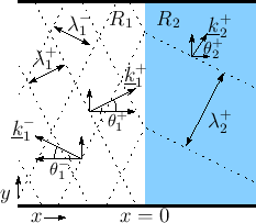
Figure C.18 shows the more general situation (as compared
to Fig.C.15) of a sinusoidal traveling plane wave
encountering an impedance discontinuity at some arbitrary angle of
incidence, as indicated by the vector wavenumber
![]() . The
mathematical details of general sinusoidal plane waves in air and
vector wavenumber are reviewed in §B.8.1.
. The
mathematical details of general sinusoidal plane waves in air and
vector wavenumber are reviewed in §B.8.1.
 |
At the boundary between impedance ![]() and
and ![]() , we have, by
continuity of pressure,
, we have, by
continuity of pressure,
as we will now derive.
Let the impedance change be in the
![]() plane. Thus, the
impedance is
plane. Thus, the
impedance is ![]() for
for ![]() and
and ![]() for
for ![]() . There are three
plane waves to consider:
. There are three
plane waves to consider:
- The incident plane wave with wave vector

- The reflected plane wave with wave vector

- The transmitted plane wave with wave vector

where
Reflection and Refraction
The first equality in Eq.![]() (C.56) implies that the
angle of incidence equals angle of reflection:
(C.56) implies that the
angle of incidence equals angle of reflection:
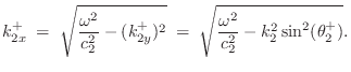
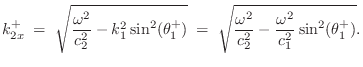
We now wish to find the wavenumber in medium 2.
Let ![]() denote the phase velocity in wave impedance
denote the phase velocity in wave impedance ![]() :
:
Evanescent Wave due to Total Internal Reflection
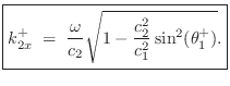
Note that if
![]() , the horizontal component
of the wavenumber in medium 2 becomes imaginary. In this case,
the wave in medium 2 is said to be evanescent, and the wave in
medium 1 undergoes total internal reflection (no power travels
from medium 1 to medium 2). The evanescent-wave amplitude decays
exponentially to the right and oscillates ``in place'' (like a
standing wave). ``Tunneling'' is possible given a
medium 3 beyond medium 2 in which wave propagation resumes.
, the horizontal component
of the wavenumber in medium 2 becomes imaginary. In this case,
the wave in medium 2 is said to be evanescent, and the wave in
medium 1 undergoes total internal reflection (no power travels
from medium 1 to medium 2). The evanescent-wave amplitude decays
exponentially to the right and oscillates ``in place'' (like a
standing wave). ``Tunneling'' is possible given a
medium 3 beyond medium 2 in which wave propagation resumes.
To show explicitly the exponential decay and in-place oscillation in
an evanescent wave, express the imaginary wavenumber as
![]() . Then we have
. Then we have
![\begin{eqnarray*}
p(t,\underline{x}) &=&
\cos\left(\omega t - \underline{k}^T\...
...-k_x x}\right\}}}\\ [5pt]
&=& e^{-k_x x} \cos(\omega t - k_y y).
\end{eqnarray*}](http://www.dsprelated.com/josimages_new/pasp/img3576.png)
Thus, an imaginary wavenumber corresponds to an exponentially decaying evanescent wave. Note that the time dependence (cosine term) applies to all points to the right of the boundary. Since evanescent waves do not really ``propagate,'' it is perhaps better to speak of an ``evanescent acoustic field'' or ``evanescent standing wave'' instead of ``evanescent waves''.
For more on the physics of evanescent waves and tunneling, see [295].
Next Section:
Longitudinal Waves in Rods
Previous Section:
Plane-Wave Scattering


