


DFT Filter Bank
Recall that the Length ![]() Discrete Fourier Transform (DFT) is
defined as
Discrete Fourier Transform (DFT) is
defined as
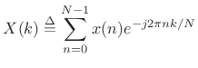 |
(10.13) |
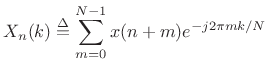
Comparing this to (9.12), we see that the filter-bank output
| (10.14) |
In other words, the filter-bank output at time
More generally, for all ![]() , we will call Fig.9.15 the DFT
filter bank. The DFT filter bank is the special case of the STFT for
which a rectangular window and hop size
, we will call Fig.9.15 the DFT
filter bank. The DFT filter bank is the special case of the STFT for
which a rectangular window and hop size ![]() are used.
are used.
The sliding DFT is obtained by advancing successive DFTs by one sample:
 |
(10.15) |
When
When ![]() is a power of 2, the DFT can be implemented using a Cooley-Tukey Fast
Fourier Transform (FFT) using only
is a power of 2, the DFT can be implemented using a Cooley-Tukey Fast
Fourier Transform (FFT) using only
![]() operations per
transform. By keeping track of the linear phase term (an
operations per
transform. By keeping track of the linear phase term (an
![]() modification), a DFT Filter Bank can be implemented efficiently using
an FFT. Uniform FIR filter banks are very often implemented in
practice using FFT software such as fftw.
modification), a DFT Filter Bank can be implemented efficiently using
an FFT. Uniform FIR filter banks are very often implemented in
practice using FFT software such as fftw.
Note that the channel bandwidths are narrow compared with half
the sampling rate (especially for large ![]() ), so that the filter bank
output signals
), so that the filter bank
output signals ![]() are oversampled, in general. We will
later look at downsampling the channel signals
are oversampled, in general. We will
later look at downsampling the channel signals ![]() to
obtain a ``hopping FFT'' filter bank. ``Sliding'' and ``hopping''
FFTs are special cases of the discrete-time Short Time Fourier
Transform (STFT). The STFT normally also uses a window
function other than the rectangular window used in this development
(the running-sum lowpass filter).
to
obtain a ``hopping FFT'' filter bank. ``Sliding'' and ``hopping''
FFTs are special cases of the discrete-time Short Time Fourier
Transform (STFT). The STFT normally also uses a window
function other than the rectangular window used in this development
(the running-sum lowpass filter).
Next Section:
Inverse DFT and the DFT Filter Bank Sum
Previous Section:
System Diagram of the Running-Sum Filter Bank


