


Modulation by a Complex Sinusoid
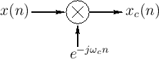
Figure 9.12 shows the system diagram for complex
demodulation.10.2The input signal ![]() is multiplied by a
complex sinusoid to produce the frequency-shifted result
is multiplied by a
complex sinusoid to produce the frequency-shifted result
| (10.8) |
Given a signal expressed as a sum of sinusoids,
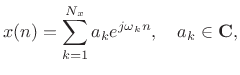 |
(10.9) |
then the demodulation produces
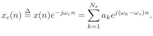 |
(10.10) |
We see that frequency
Next Section:
Making a Bandpass Filter from a Lowpass Filter
Previous Section:
The Running-Sum Lowpass Filter


