


A poor man's Simulink
Glue between Octave and NGSPICE for discrete- and continuous time cosimulation (download)
Keywords: Octave, SPICE, Simulink
Introduction
Many DSP problems have close ties with the analog world. For example, a switched-mode audio power amplifier uses a digital control loop to open and close power transistors driving an analog filter.
There are commercial tools for digital-analog cosimulation: Simulink comes to mind, and mainstream EDA vendors support VHDL-AMS or Verilog-A in their simulators.
The main disadvantage is the substantial price tag. Also, casual use of commercial tools with the unavoidable licensing restrictions is a known recipe for future headaches and hair loss.
In this article, I'll show an alternative that relies only on open-source tools:
NGSPICE as continuous-time simulator is embedded into Octave for DSP and control.
It seems useful as simple, low-cost solution for research and system design work.
While the overall idea isn't complex, making it actually work was not a smooth ride:
The underlying code went through half a dozen iterations with three different simulators and multiple interfacing mechanisms before it worked reliably. With a length of about three screens it is even quite compact.
As the conventional MEX interface is used, integration to Matlab should be straightforward (it might even work out of the box) but I'm making no promises here.
Example
The RC circuit in figure 1 shows a simple lowpass filter:
From its initial value of 0 Volts, the voltage at node n2 follows the input voltage V1 slowly.
The theoretical output is an exponential function with a time constant of RC=100 ns.

Figure 1: RC lowpass
My example control algorithm implements the following functionality:
- Charge with 5V source voltage until capacitor voltage reaches 3V
- Discharge with 0V source voltage until capacitor voltage reaches 1V
- Charge again with 5V source voltage for 300 ns
In digital terms, this demonstrates both synchronous and asynchronous events (triggered by time and circuit state, respectively).
In the top-level Octave script, the controls are implemented as follows (figure 2):
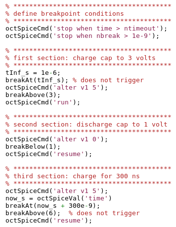
Figure 2: Code example in Octave
run and resume are SPICE commands that start a simulation and continue it after it has stopped at a breakpoint.
This example is meant only to give an overview. The details are documented in code and netlist.
For example, the Octave user function breakAbove sends an alter command to the SPICE simulator to modify polarity and level of a breakpoint condition at the capacitor.
octSpiceXyz statements are C-language interface functions (.mex) between Octave and NGSPICE.
Running the simulation gives the following result:
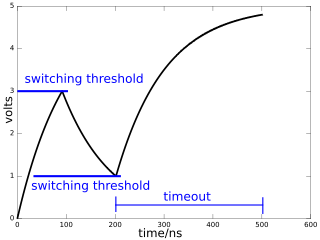
Figure 3: simulation result
As expected, the voltage switches direction twice, and the simulation terminates after another 300 ns.
The circuit could be easily modified for example into a switched-mode DCDC converter by adding an inductor.
It is interesting to note that SPICE isn't limited to electrical circuits:
Many non-electrical problems (e.g. mechanical) lead to differential equations that are similar to those of electrical circuits and can be modeled by an equivalent electrical circuit.
At a more abstract level, the XSPICE extensions (a compile time option of nspice) provide generic behavioral modeling blocks, such as multipliers, summers, integrators, and turn it into a fairly versatile continuous-time simulator.
So what is SPICE?
The SPICE circuit simulator is a tool for modeling the complex and nonlinear interactions in electrical circuits.
Its long and colorful history began more than four decades ago, and it largely defined today's languages for circuit netlists.
With the charm of a relic from the last ice age, it remains a very capable and sophisticated piece of software despite its quirks (and the occasional punch card reference).
Its robust integration algorithm and availability made it popular also for non-electrical problems.
In so-called "transient" mode, SPICE solves continuous-time differential equations by numeric integration.
An important feature, when approached with a DSP mindset, is the adaptive step size control:
A discontinuity, such as changing a digital sample, causes momentarily high-frequency signal content that requires integration along smaller time steps.
Fast transients tend to decay quickly, and the simulator increases its step size, trying to balance accuracy and speed.
The adaptive step size control is one fundamental difference to the "digital" world with a synchronous clock.
There is no well-defined Nyquist limit, and aliasing typically hides in the integration error.
The open-source variant NGSPICE is a descendant of the original SPICE code. Its manual can be found here.
Cosimulation
The simulator is controlled using breakpoints in the form of nnode > nref, where the n are node voltages.
Deleting breakpoints in NGSPICE is currently unreliable (risk of segfaults) but modifying a voltage source to change nref in an existing breakpoint is safe.
A timed breakpoint is implemented using the simulator's time variable and a constant threshold voltage.
Simulation returns when any single breakpoint is triggered.
The controlling Octave script is responsible to clear all breakpoint conditions (i.e. set a near-infinite trigger level that is never reached), otherwise SPICE would perform only a minimum-length time step and return.

Figure 4: Simulator interaction
Octave interface
The Octave script interacts with SPICE through the following functions:
- octSpiceCmd(text): Sends a command to SPICE.
Also initializes simulator on the first invocation. - octSpiceVal(nodename): Retrieves the last value of a node.
Capital letters in the net list are converted by SPICE to small letters (myNode100 becomes mynode100).
The current of a voltage source is identified by i(vmysource).
time refers to simulation time.
A simple way to find all node names is to save the state to file via octSpiceCmd('write rawspice.raw');, then read the ASCII header of the .raw file in a text editor. - octSpiceVec(nodename): Same as octSpiceVec(nodename) but recalls the whole history as vector.
Note that the time step may vary.
Installation
Requirements:
- An octave installation with functional mkoctfile
- ngspice with ./configure --with-ngshared --enable-xspice
The --enable-ngshared flag builds Ngspice as shared library only. To get also the standard executables ngspice and nutmeg, do ./configure; make; make install a second time without the option.
If mkoctfile is missing, building the latest octave from source is quickly done on Linux after installing all dependencies using apt-get build-deps octave.
The code was tested under Ubuntu Linux (in a virtual Box under Windows) using Octave 3.8-2.
Building Octave from source (i.e. to work with the latest version of OctaveForge) is fairly straighforward when dependencies have been installed once via sudo apt-get build-dep octave.
The included makefile compiles the .mex interface functions. If everything goes according to plan,
make
make test
should run the example simulation and show plotted results. Keep fingers crossed.
Concluding remarks
The integration of SPICE as continuous-time simulator provides a powerful tool to simulate digital algorithms that are tightly coupled with analog functionality.
Between digital events, there is no other overhead to the SPICE simulator than the breakpoint(s).
Typical use cases are nonlinear and/or time variant (e.g. clock-switched switched) systems, such as digital controls of analog systems or asynchronous events, e.g. switching converters.
However, it is worth to point out that for simple LTI circuits (such as the shown RC lowpass), there is an alternative approach that avoids cosimulation:
Simulate the continuous-time impulse response, sample it at the desired sampling rate and use it as equivalent model in a purely discrete-time simulator.
Download


- Comments
- Write a Comment Select to add a comment

Python environment packages:
MyHDL: http://www.myhdl.org
eispice: http://www.thedigitalmachine.net/eispice.html
Example combined simulation,
http://old.myhdl.org/doku.php/projects:mixedmodesimulation
To post reply to a comment, click on the 'reply' button attached to each comment. To post a new comment (not a reply to a comment) check out the 'Write a Comment' tab at the top of the comments.
Please login (on the right) if you already have an account on this platform.
Otherwise, please use this form to register (free) an join one of the largest online community for Electrical/Embedded/DSP/FPGA/ML engineers:


