


Improved Narrowband Lowpass IIR Filters
Here's a neat IIR filter trick. It's excerpted from the "DSP Tricks" chapter of the new 3rd edition of my book "Understanding Digital Signal Processing". Perhaps this trick will be of some value to the subscribers of dsprelated.com.
Due to their resistance to quantized-coefficient errors, traditional 2nd-order infinite impulse response (IIR) filters are the fundamental building blocks in computationally-efficient high-order IIR digital filter implementations. However, when used in fixed-point number systems, the inherent properties of quantized-coefficient 2nd-order IIR filters do not readily permit their use in narrowband lowpass filtering applications. Narrowband lowpass IIR filters have traditionally had a bad reputation—for example, MATLAB's Signal Processing Toolbox documentation warns: "All classical IIR lowpass filters are ill-conditioned for extremely low cutoff frequencies."
Here we present a neat trick to overcome the shortcomings of narrowband 2nd-order lowpass IIR filters, with no increase in filter coefficient bit widths and no increase in the number of filter multiplies per output sample.
The Problem with Narrowband Lowpass IIR Filters
Narrowband lowpass IIR filters are difficult to implement because of intrinsic limitations on their z-plane pole locations. Let's examine the restrictions on the z-plane pole locations of a standard 2nd-order IIR filter whose structure is shown in Figure 1(a).
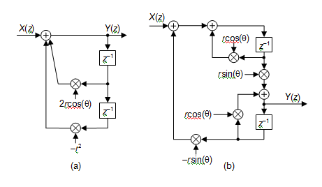
Figure 1 Second-order IIR filters: (a) standard form; (b) coupled-form.
Such an IIR filter, having a transfer function given by
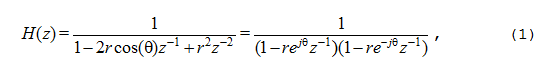
has a pair of conjugate poles located at radii of r, at angles of ±θ radians. (For filter stability reasons, we always ensure that r < 1.) In fixed-point implementations, quantizing the 2rcos(θ) and –r2 coefficients restricts the possible pole locations [1,2]. On the z-plane, a pole can only reside at the intersection of a vertical line defined by the quantized value of 2rcos(θ) and a concentric circle whose radius is defined by the square root of the quantized value of r2. For example, Figure 2 shows the first quadrant of possible z-plane pole locations using five magnitude bits to represent the filter's two coefficients. Notice the irregular spacing of those permissible pole locations. (Due to trigonometric symmetry, the pole locations in the other three quadrants of the z-plane are mirror images of those shown in Figure 2.)
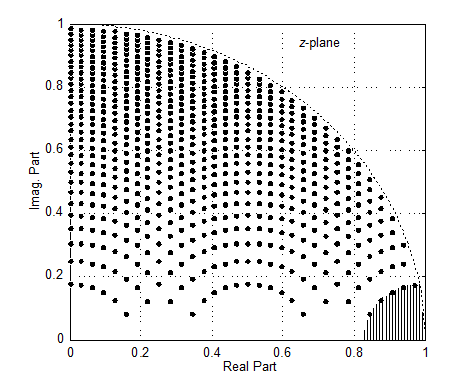
Figure 2 Possible pole locations for five magnitude-bit coefficient quantization.
So here's the problem we have with standard 2nd-order IIR filters: if we use floating-point software to design a very narrowband (high-order) lowpass IIR filter (implemented as cascaded 2nd-order filters) having poles residing in the shaded area near z = 1, subsequent quantizing of the designed filter coefficients to five magnitude bits will make the poles shift to one of the locations shown by the dots on the border of the shaded region in Figure 2. Unfortunately that pole shifting, inherent in the Figure 1(a) IIR filter implementation due to coefficient quantization in fixed-point systems, prevents us from realizing the desired narrowband lowpass filter. We can always reduce the size of the shaded forbidden zone near z = 1 in Figure 2 by increasing the number of bits used to represent the 2nd-order filters' coefficients. However, in some filter implementation scenarios increasing coefficient binary-word bit widths may not be a viable option.
One solution to the above problem is to use the so-called coupled-form IIR filter (also called the Gold-Rader filter [3]) structure, shown in Figure 1(b), having a transfer function given by
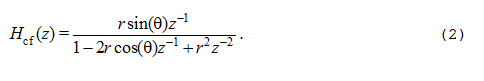
Because the coupled-form filter's quantized coefficients in Figure 1(b) are linear in rcos(θ) and rsin(θ), its possible pole locations are on a regularly-spaced grid on the z-plane defined by z = rcos(θ) + jrsin(θ). This enables us to build 2nd-order narrowband lowpass IIR filters with poles in the desired shaded region of Figure 2.
This pole placement behavior is a beautiful example of the difference between apparently-equivalent filter implementations. With infinite-precision coefficients the standard and coupled-form IIR filters, having identical denominators in their transfer functions, will have identical z-plane pole locations. But with quantized coefficients the two filters will have different poles locations.
Back to our problem. While the coupled-form IIR filter gives us increased flexibility in placing z-plane poles for lowpass filtering, unfortunately, this coupled-form implementation requires twice the number of multiplies needed by the standard 2nd-order IIR filter in Figure 1(a).
In the following material we describe a slick narrowband lowpass IIR filter structure, proposed by Harris and Loudermilk, having poles residing in the shaded region of Figure 2 with no increase in coefficient bit width and no additional multiplication operations beyond those needed for a standard 2nd-order IIR filter [4].
An Improved Narrowband Lowpass IIR Filters
The improved lowpass IIR filter is created by replacing each unit-delay element in a standard 2nd-order IIR filter with multiple unit-delay elements as shown in the left portion of Figure 3. This zero-stuffed IIR filter will retain its original lowpass passband and have multiple passband images, exactly as happens with interpolated finite impulse response (IFIR) filters [5-7]. The zero-stuffed IIR filter is followed by a lowpass image-reject filter that attenuates those unwanted passband images. Given this cascaded structure, which we'll demonstrate shortly, we call the filter combination in Figure 3 an interpolated infinite impulse response (interpolated-IIR) filter.
The M-length delay lines, where M is a positive integer, in the zero-stuffed IIR filter shift a standard IIR filter's conjugate poles, originally located at z = re±jθ, to the new locations of
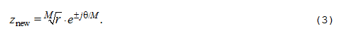
That is, the new conjugate pole locations are at radii of the Mth root of r, at angles of ±θ /M radians. Happily, those interpolated-IIR filter pole locations can now reside in the desired shaded region of Figure 2 without using more bits to represent the zero-stuffed IIR filter's coefficients.
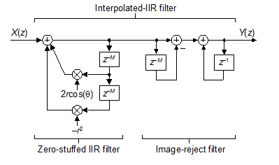
Figure 3 Interpolated-IIR filter.
If the original Figure 1(a) 2nd-order IIR filter contains feedforward coefficients, those coefficients are also delayed by M-length delay lines.
Interpolated IIR Filter Example
Let's show an example of an interpolated-IIR filter in action. With fs representing a filter's input signal sample rate in hertz, assume we want to implement a recursive lowpass filter whose one-sided passband width is 0.005fs with a stopband attenuation greater than 60 dB. If we choose to set M = 4, then we start our interpolated-IIR filter design process by first designing an standard IIR filter having a one-sided passband width of M•0.005fs = 0.02fs. Using our favorite IIR filter design software (for an elliptic IIR filter in this example), we obtain a fifth-order prototype IIR filter. Partitioning that fifth-order prototype IIR filter into two 2nd-order and one single-order IIR filter sections, all in cascade and having coefficients represented by 12-bit words, yields the frequency magnitude response shown in Figure 4(a).
Next, replacing the unit-delay elements in the filter sections with M = 4 unit-delay elements results in the frequency magnitude response shown in Figure 4(b). There we see the multiple narrowband passband images induced by the M = 4 length delay lines of the interpolated-IIR filter. Our final job is to attenuate those unwanted passband images. We can do so by following the cascaded increased-delay IIR filter sections with a cascaded integrator-comb (CIC) filter, whose structure is shown on the right side of Figure 3. (The CIC filter is computationally advantageous because it requires no multiplications.)
To satisfy our desired 60 dB stopband attenuation requirement, we use a 2nd-order CIC filter—two first-order CIC filters in cascade—to attenuate the passband images in Figure 4(b). The result of our design is the interpolated-IIR and CIC filter combination whose composite frequency magnitude response meets our filter requirements as shown Figure 4(c).
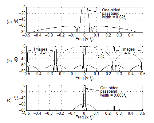
Figure 4 Frequency magnitude responses: (a) original IIR prototype filter; (b) zero-stuffed interpolated-IIR filter and CIC filters (dashed); (c) final narrowband 12-bit coefficient filter.
In practice, 2nd-order subfilters may have large gains requiring unpleasantly large bit-width multipliers and large bit-width registers to store intermediate results. For this reason it may be necessary to scale the IIR subfilters' coefficients as discussed in Chapter 6, or truncate the subfilters' output samples, in order to avoid undesirably large bit-width processing.
To recap this material, we discussed the limitations encountered when using traditional 2nd-order quantized-coefficient IIR filters to perform narrowband lowpass filtering, and mentioned the coupled-form IIR filter that reduced those limitations albeit with an increased computational cost of doubling the number of multiplies per filter output sample. Next we described, and then demonstrated, an interpolated-IIR filter that overcomes the shortcomings of traditional lowpass IIR filters. The interpolated-IIR filter provides improved lowpass IIR filter performance while requiring no increase in filter coefficient bit widths and no additional multiply operations beyond a traditional IIR filter. When it comes to narrowband lowpass IIR filters, there's a new sheriff in town.
References
[1] Proakis J. and Manolakis D., Digital Signal Processing-Principles, Algorithms, and Applications, 3rd Ed., Prentice Hall, Upper Saddle River, New Jersey, 1996, pp. 572–576.
[2] Oppenheim A. and Schafer R., Discrete-Time Signal Processing, 2nd Ed., Prentice Hall, Englewood Cliffs, New Jersey, 1989, pp. 382–386.
[3] Gold B. and Rader C., "Effects of Parameter Quantization on the Poles of a Digital Filter", Proceedings IEEE, Vol. 55, pp. 688–689, May 1967.
[4] Harris F. and Lowdermilk W., "Implementing Recursive Filters with Large Ratio of Sample Rate to Bandwidth", in Conference Record of the Forty-First Asilomar Conference on Signals, Systems and Computers, Pacific Grove, CA, Nov. 4–7, 2007, pp. 1149–1153.
[5] Losada, R., "Design Finite Impulse Response Digital Filters ", http://mwrf.com/Articles/Index.cfm?ArticleID=7469&pg=3
[6] Lyons, R., "Interpolated Finite Response Filters", http://www.danvillesignal.com/files/compdsp_Lyons_Viewgraphs_IFIR.pdf
[7] Lyons, R., Interpolated narrowband lowpass FIR filters, IEEE Signal Processing Magazine, Jan. 29, 2004


- Comments
- Write a Comment Select to add a comment
To post reply to a comment, click on the 'reply' button attached to each comment. To post a new comment (not a reply to a comment) check out the 'Write a Comment' tab at the top of the comments.
Please login (on the right) if you already have an account on this platform.
Otherwise, please use this form to register (free) an join one of the largest online community for Electrical/Embedded/DSP/FPGA/ML engineers:


