


Generating Complex Baseband and Analytic Bandpass Signals
There are so many different time- and frequency-domain methods for generating complex baseband and analytic bandpass signals that I had trouble keeping those techniques straight in my mind. Thus, for my own benefit, I created a kind of reference table showing those methods. I present that table for your viewing pleasure in this blog.
For clarity, I define a complex baseband signal as follows: derived from an input analog xbp(t)bandpass signal whose spectrum is shown in Figure 1(a), or discrete input xbp(n) bandpass signal whose spectrum is shown in Figure 1(b), a complex baseband signal is an xBB(n) sequence whose spectrum is that shown in Figure 1(c). The sample rate of an xbp(n) input sequence is defined as fs Hz.
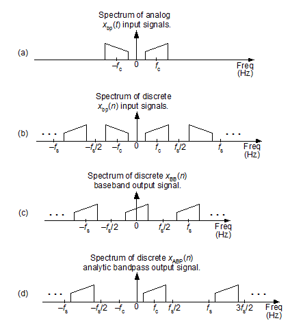
Figure 1.
Based on the same analog xbp(t) or discrete xbp(n) input bandpass signal, an analytic bandpass signal is an xABP(n) sequence whose spectrum is that shown in Figure 1(d).
I realize that, by strict definition, an analytic signal has no negative-frequency spectral energy. And because our xABP(n) output bandpass signal is a discrete sequence it has spectral replications in its negative-frequency spectral region—so calling xABP(n) an analytic signal seems incorrect. We'll bypass that controversy by saying that a discrete sequence is analytic if it has no spectral energy in the frequency range of –fs/2 to zero Hz.
Table 1, below, presents my Hit Parade of complex baseband and analytic bandpass signal generation methods. In that table "LPF" means a lowpass, linear-phase, tapped-delay line, FIR filter. All discrete Fourier transforms (DFTs) are implemented with radix-2 fast Fourier transforms (FFTs).
Table 1: Complex baseband and analytic bandpass signal generation methods
|
Process |
Input/Output |
Comments |
|
Quadrature Sampling
|
Input: analog bandpass signal centered at fc Hz, with sample rate of fs Hz..
Output: discrete complex xBB(n) baseband signal, centered at zero Hz, with sample rate of fs Hz. |
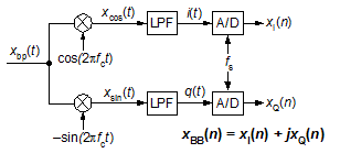
Uses analog mixing and analog lowpass filters. Difficult to control the exact phase delays and gains of the i(t) and q(t) signals. |
|
Quadrature Sampling
|
Input: analog bandpass signal centered at fc Hz, with sample rate of fs Hz.
Output: discrete complex xBB(n) baseband signal, centered at zero Hz, with sample rate of fs Hz. |
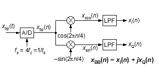
All-digital downconversion facilitates exact control of phases and gains of the xI(n) and xQ(n) signals. A/D's fs sample rate normally equal to 4fc, but setting fs = 0.8fc allows bandpass sampling to reduce the fs sample rate. fs must greater than twice the bandwidth of xbp(t). See [1] or Section 8.9 of [2]. |
|
Discrete Complex Downconversion
|
Input: discrete real bandpass signal centered at fs/4 Hz, with sample rate of fs Hz.
Output: discrete complex xBB(n) baseband signal, centered at zero Hz, with sample rate of fs/4 Hz. |
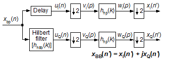
Uses a time-domain Hilbert transformer and a half-band highpass FIR filter. If hhilb(k) has an odd number of taps, then half its coefficients will be zero-valued. See [3] or Section 13.43 of [2]. |
|
Discrete Complex Downconversion
|
Input: discrete real bandpass signal centered at fs/4 Hz, with sample rate of fs Hz.
Output: discrete complex xBB(n) baseband signal, centered at zero Hz, with sample rate of fs/4 Hz. |
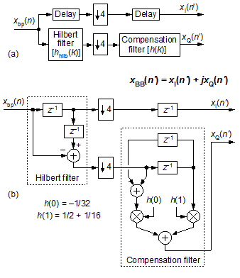
Uses a time-domain Hilbert transformer and simple three-tap highpass FIR compensation filter as shown in Part (a) of figure. Efficient implementation shown in Part (b) of figure. For reasonably acceptable operation, the bandwidth of xbp(n) must not be larger than, say, fs/10. See Section 13.43 of [2]. |
|
Discrete Complex Downconversion
|
Input: discrete real bandpass signal centered at fs/4 Hz, with sample rate of fs Hz..
Output: discrete complex xBB(n) baseband signal, centered at zero Hz, with sample rate of fs/2 Hz. |
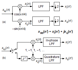
Standard complex downconversion and lowpass FIR filtering, with decimation by two as shown in Part (a) of figure. Due to the decimation, a very efficient implementation is that shown in Part (b) of figure. The coefficients of the In-phase and Quadrature phase LPFs are decimated versions of the coefficients in the identical Part (a) LPFs. If the Part (a) LPFs are half-band filters, the Part (b) In-phase and Quadrature phase LPFs will be even more computationally efficient. See [4], [5], or Section 13.1.3 of [2]. |
|
Discrete Complex Downconversion
|
Input: discrete real bandpass signal centered at fc Hz, with sample rate of fs Hz.
Output: discrete complex xBB(n) baseband signal, centered at zero Hz, with sample rate of fs Hz. |
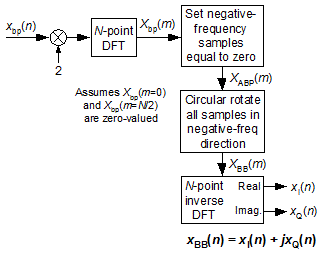
Negative-frequency components of xbp(n) are attenuated in the frequency domain. Frequency downconversion performed by shifting (rotating) the frequency-domain indices of the positive-frequency spectral samples prior to inverse DFT. |
|
Discrete Complex Downconversion
|
Input: discrete real bandpass signal centered at kfs/D Hz, with sample rate of fs Hz.
Output: discrete complex xBB(n) baseband signal, centered at zero Hz, with sample rate of fs/D Hz. |
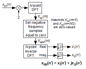
Negative-frequency components of xbp(n) are attenuated in the frequency domain. Frequency downconversion performed by decimation in the time domain. See Section 13.29 of [2].
|
|
Analytic Bandpass Signal Generation
|
Input: discrete bandpass signal centered at fc Hz, with sample rate of fs Hz.
Output: discrete analytic xABP(n) bandpass signal, centered at fc Hz, with sample rate of fs Hz. |
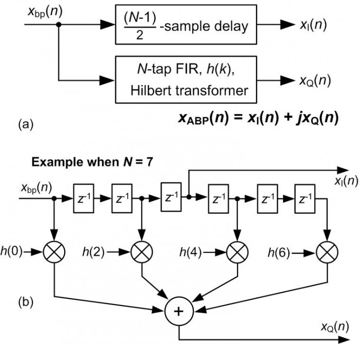
Standard time-domain, tapped-delay line, FIR Hilbert transform method of discrete analytic bandpass signal generation. For proper time synchronization of xI(n) and xQ(n), N must be an odd number—in which case half the h(k) coefficients will be zero-valued. See Note 61 of [7] or Section 9.4.1 of [2]. |
|
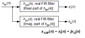
Analytic Bandpass Signal Generation
Windowing the two sets of filter coefficients will minimize passband magnitude differences between the hcos(k) and hsin(k) filters. (This method has slightly improved aggregate (overall) negative frequency attenuation compared to the following A(k) and B(k) dual filter method.) |
Input: discrete bandpass signal centered at fc Hz, with sample rate of fs Hz.
Output: discrete analytic xABP(n) bandpass signal, centered at fc Hz, with sample rate of fs Hz. |
A prototype lowpass filter (LPF) is designed to have a two-sided bandwidth slightly greater than the bandwidth of xbp(n). The LPF's coefficients are multiplied by cosine and sine sequences whose frequencies are fc Hz, creating a positive-frequency complex hbp(k) bandpass filter. If fc = fs/4 then half the LPF coefficients will be zero-valued. Using a half-band LPF, if possible, further enhances computational efficiency. See [6], Note 62 of [7], or Section 9.5 of [2]. |
|
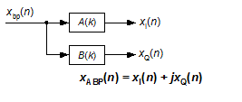
Analytic Bandpass Signal Generation
The A(k) and B(k) filters have guaranteed equal magnitude responses. B[k] coefficients are a reversed-ordered version of the A[k] coefficients (reduces coefficient storage requirement). |
Input: discrete bandpass signal centered at fc Hz, with sample rate of fs Hz.
Output: discrete analytic xABP(n) bandpass signal, centered at fc Hz, with sample rate of fs Hz. |
Clay Turner's method of designing two orthogonal real bandpass filters, that when combined yield a positive-frequency complex filter. If filters are centered at fs/4 and have an even number of taps, then half the A[k] and B[k] coefficients will be zero-valued. Phase responses of A[k] and B[k] filters are very nearly, but not quite exactly, linear. See [8] for equations used to compute A(k) and B(k) coefficients. |
|
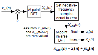
Analytic Bandpass Signal Generation
|
Input: discrete bandpass signal centered at fc Hz, with sample rate of fs Hz.
Output: discrete analytic xABP(n) bandpass signal, centered at fc Hz, with sample rate of fs Hz. |
Straightforward frequency-domain method of bandpass analytic signal generation. Negative-frequency spectral components of Xbp(m) are set to zero creating the desired analytic signal's spectrum. See [9] or Section 9.4.2 of [2]. |
|
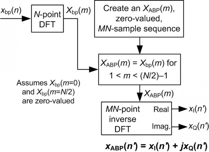
Interpolated Analytic Bandpass Signal Generation |
Input: discrete bandpass signal centered at fc Hz, with sample rate of fs Hz.
Output: interpolated discrete xABP(n) analytic bandpass signal, centered at fc Hz, with sample rate of Mfs Hz. |
Frequency-domain method of interpolated by M bandpass analytic signal generation. Negative-frequency spectral components of Xbp(m) are set to zero creating the desired analytic signal's spectrum. New spectrum is zero-stuffed, prior to inverse DFT, to achieve time-domain interpolation by factor M. See Section 13.28.2 of [2]. |
For completeness, I mention that DSP pioneer Charles Rader proposed a computationally-efficient analytic bandpass signal generation method (See [10] or Note 66 in [7]) where both its xI(n) and xQ(n) output channels have identical frequency magnitude responses, however that scheme does not exhibit a linear-phase frequency response. As such, I didn't include it in Table 1.

References
[1] Considine, V. “Digital Complex Sampling,” Electronics Letters, 19, August 4, 1983.
[2] Lyons, R. Understanding Digital Signal Processing, Prentice Hall Publishing, Hoboken, NJ, 2010.
[3] Ohlsson, H., et al. “Design of a Digital Down Converter Using High Speed Digital Filters,” in Proc. Symp. on Gigahertz Electronics, Gothenburg, Sweden, March 13–14, 2000, pp. 309–312.
[4] Powell, S. “Design and Implementation Issues of All Digital Broadband Modems,” DSP World Workshop Proceedings, Toronto, Canada, September 13–16, 1998, pp. 127–142.
[5] Frerking, M. Digital Signal Processing in Communications Systems, Chapman & Hall, New York, 1994, p. 330.
[6] Reilly, A., et. al. “Analytic Signal Generation—Tips and Traps,” IEEE Trans. on Signal Proc., Vol. 42, No. 11, Nov. 1994.
[7] Rorabaugh, C. Notes on Digital Signal Processing: Practical Recipes for Design, Analysis and Implementation, Prentice Hall Publishing, Hoboken, NJ, 2010.
[8] Turner, C. "An Efficient Analytic Signal Generator", IEEE Signal Processing Magazine, DSP Tips & Tricks column, July 2009.
[9] Marple, S., Jr. “Computing the Discrete-Time ‘Analytic’ Signal via FFT,” IEEE Trans. on Signal Proc., Vol. 47, No. 9, September 1999, pp. 2600–2603.
[10] Rader, C. “A Simple Method for Sampling In-Phase and Quadrature Components,” IEEE Trans. Aerospace and Electronic Syst., Vol. 20, No. 6, pp. 821-824, Nov. 1984.


- Comments
- Write a Comment Select to add a comment
sameer babu
http://ieeexplore.ieee.org/xpl/login.jsp?tp=&arnumber=1193158&url=http%3A%2F%2Fieeexplore.ieee.org%2Fxpls%2Fabs_all.jsp%3Farnumber%3D1193158
To post reply to a comment, click on the 'reply' button attached to each comment. To post a new comment (not a reply to a comment) check out the 'Write a Comment' tab at the top of the comments.
Please login (on the right) if you already have an account on this platform.
Otherwise, please use this form to register (free) an join one of the largest online community for Electrical/Embedded/DSP/FPGA/ML engineers:


