


Instant CIC
Summary:
A floating point model for a CIC decimator, including the frequency response.
Description:
A CIC filter relies on a peculiarity of its fixed-point implementation: Normal operation involves repeated internal overflows that have no effect to the output signal, as they cancel in the following stage.
One way to put it intuitively is that only the speed (and rate of change) of every little "wheel" in the clockworks carries information, but its absolute position is arbitrary.
Modeling a CIC filter without use of bit-accurate numbers is not completely straightforward. Here, I'll show some "instant" solution for the decimating variant. Just add water and stir.
The good. The bad. The ugly.
Let's start with "ugly".
The "time domain" implementation (complete code below) is what I get when I close my eyes to the numerical overflow problem and simply write the CIC difference equations with floats.
Now double precision arithmetics are quite forgiving, and it works well enough.
It should do fine for a classroom demo (and please don't use it in the next Mars mission).
Then, the "frequency domain" implementation:
- Take the FFT of the signal (assuming for simplicity it wraps around at the end - one cycle of an infinitely periodic signal - Fourier theory applies)
- evaluate the known frequency response of a CIC filter at the FFT frequency bins. Reference: [1], eq. 3
- Multiply
- Use IFFT to go back to the time domain
- Decimate
This is only "bad", as taking the FFT of the whole signal all at once might be inconvenient.
Finally, what I'd consider a "good" solution:
- Evaluate the impulse response before decimation
- Apply the impulse response using an off-the-shelf FIR filter component, i.e. filter() command in Octave / Matlab
- Decimate
The approach is accurate, as despite its internal recursion, the impulse response of a CIC filter has a finite length (it is of FIR type, not IIR).
To apply the impulse resonse b to an input sequence x, use y = filter(b, 1, x);
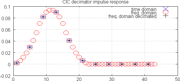
Plot:
The plot shows that all three methods give exactly the same impulse response (accurate to ~10-15). Decimating discards three samples out of four, leaving only red-trace samples that coincide with the other two traces.
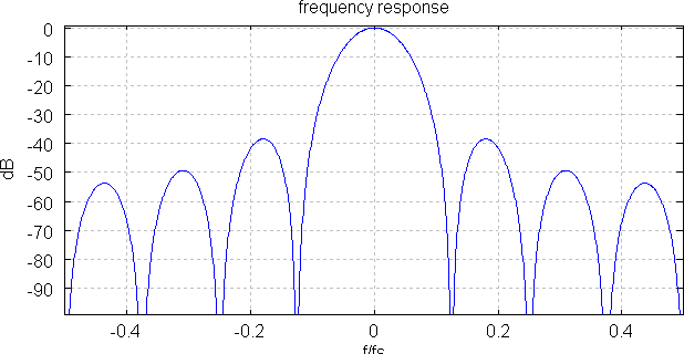
Frequency response:
The frequency response is evaluated on the higher (input) rate. Therefore, it is straightforward to investigate the rejection on input frequencies that will cause aliasing, once decimated.
Conclusion
The example shows how to model a CIC decimator in floating point as a conventional FIR filter by sampling the finite-length impulse response.
Download:
Code:
% CIC decimator example
% includes
% - time domain implementation
% - frequency domain model via z-domain transfer function
% Parameters:
% R = rate change factor
% N = nStages
% M = differential delay
% reference: [1] http://www.altera.com/literature/an/an455.pdf

function instantCIC()
 close all;
 testvec = zeros(1, 43);
 R = 4;
 testvec(1) = 1;
 N = 3;
 M = 2;
 a = CICdec_timeDomainModel(testvec, N, M, R);
 [b, H] = CICdec_freqDomainModel(testvec, N, M, R, false);
 [c, H] = CICdec_freqDomainModel(testvec, N, M, R, true);

 figure(1); grid on; hold on;
 plot(1:R:R*numel(a), a, 'bx');
 plot(b, 'ro');
 plot(1:R:R*numel(c), c, 'k+');
 title('CIC decimator impulse response');
 legend('time domain', 'freq. domain', 'freq. domain decimated');

 % plot
 H = fft([ifft(H), zeros(1, 1000)]); % zero-padding
 figure(2); clf(); grid on; hold on;
 plot(linspace(-0.5, 0.5, numel(H)), fftshift(20*log10(abs(H) + 1e-15)), 'b');
 xlim([-0.5, 0.5]);
 title('frequency response');
 xlabel('f/fs');
 ylabel('dB');
end

function [vec, H] = CICdec_freqDomainModel(vec, N, M, R, doDecim)
 flag = isreal(vec);

 % evaluate frequency response (z-domain transfer function)
 n = numel(vec);
 zInv = exp(-2i*pi*(0:(n-1))/n);
 b = ones(1, R * M);
 H = polyval(b, zInv) .^ N;
 H = H / H(1);

 % apply frequency response
 vec = ifft(fft(vec) .* H);

 % decimate
 if doDecim
 vec = vec(1:R:end);
 end

 % don't let FFT roundoff error turn real signal into complex
 if flag
 vec = real(vec);
 end
end

function vec = CICdec_timeDomainModel(vec, N, M, R)
 nLeadIn = M * N * R;
 nLeadOut = nLeadIn / R;
 ix = mod(-nLeadIn:-1, numel(vec)) + 1;

 % prepend end of cyclic signal
 vec = [vec(ix) vec];

 % integrator
 for ix = 1:N
 vec = cumsum(vec);
 end

 % decimator
 vec = vec(1:R:end);

 % differentiator
 for ix = 1:N
 vec = vec - circshift(vec, [0, M]);
 end

 % remove the added length
 vec = vec(nLeadOut+1:end);

 % scale gain
 gain = (R * M) .^ N;
 vec = vec / gain;
end


- Comments
- Write a Comment Select to add a comment


To post reply to a comment, click on the 'reply' button attached to each comment. To post a new comment (not a reply to a comment) check out the 'Write a Comment' tab at the top of the comments.
Please login (on the right) if you already have an account on this platform.
Otherwise, please use this form to register (free) an join one of the largest online community for Electrical/Embedded/DSP/FPGA/ML engineers:


