


How Not to Reduce DFT Leakage
This blog describes a technique to reduce the effects of spectral leakage when using the discrete Fourier transform (DFT).
In late April 2012 there was a thread on the comp.dsp newsgroup discussing ways to reduce the spectral leakage problem encountered when using the DFT. One post in that thread caught my eye [1]. That post referred to a website presenting a paper describing a DFT leakage method that I'd never heard of before [2]. (Of course, not that I've heard everything there is to hear about DFT leakage.)
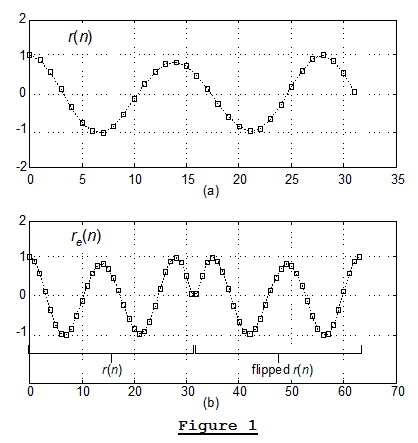
The paper's author presents a method for reducing spectral leakage when an r(n) input sequence is applied to the DFT. In that method, a left-to-right time-flipped version of r(n) is appended to the original r(n) sequence creating a new re(n) sequence with twice as many samples as r(n). As I understand the idea, the below Figure 1(a) shows an example of a 32-sample r(n) time sequence and Figure 1(b) shows the 'leakage reduction' method's resulting 'data-flipped' 64-sample re(n) time sequence.
According to the paper's author, when re(n) is applied to the DFT, its DFT results will exhibit reduced spectral leakage compared to the DFT results of the original r(n). In addition, the author stated that the DFT of the re(n) sequence will have the same spectrum as the DFT of the original r(n) sequence. Reading those later words made me suspicious. As it turned out, many things in that paper bothered me—bothered me a lot—but I won't bore you with the details.
Wait a second, ... I will mention one thing that is truly important. The paper's author stated that the purpose of windowing is to ensure that the first and last samples of a windowed time sequence are zero-valued. That statement is not correct. The fact that the first and last samples of a windowed time sequence are zero-valued is an effect of windowing, not the goal of windowing. The goal of windowing is to reduce the amplitude discontinuities in a circular version of a DFT's input sequence. Stated in different words, if you created a repetitive version of the windowed time sequence, by repeating the windowed sequence over and over, the goal of windowing is to reduce the amplitude discontinuities in that repetitive sequence. Now in fairness, I'll admit that the author's mistaken conclusion about the purpose of windowing is an easy mistake to make.
What troubled me most was that in my Matlab simulations of that data-flipping spectral leakage reduction method is that I found a case where it does not work properly! For example, when a 183 Hz sinusoidal r(n) was used as the input to the data-flipping leakage reduction method the resulting frequency response is that shown by the solid curve in Figure 2. (The fs sample rate of r(n) was 1000 Hz.) For reference purposes, the dashed curve in Figure 2 is the spectrum of r(n) windowed by a Hanning window. Notice two things: (1) the sidelobe levels of the data-flipping scheme are far higher than the sidelobes in the Hanning windowed spectrum; (2) the troubling dip in the mainlobe of the data-flipping method's frequency response.
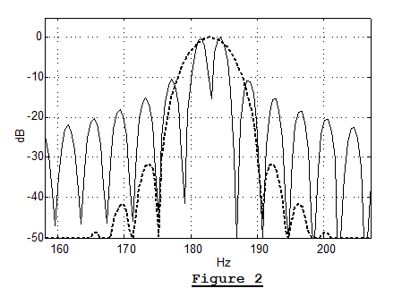
I believe the problem with the paper's data-flipping leakage reduction method is as follows: Where the frequency transforms of the standard Hanning and Hanning windows are not dependent on the frequency of a time sequence to which they're applied, the paper's data-flipping leakage reduction method DOES depend on the frequency of an input r(n) sequence.
So, ...if I understand the paper's technique correctly, I'd never recommend that it be used in practice.

Postscript:
One of the subscribers here, nairen, posted a comment giving the frequency response of the 'data-flipping' process. A PDF file of nairen's very clever derivation can be downloaded by clicking here.
References
[1] From: "Lightbulb85", Subject: Re: Reducing Spectral Leakage of Rectangular Window?, Date: Thu, 26 Apr 2012.
[2] http://www.slac.stanford.edu/cgi-wrap/getdoc/slac-pub-6221.pdf


- Comments
- Write a Comment Select to add a comment

However, if the turning angle is too sharp (less than or near 90°), it may still cause a slope interruption, and the end effect may appear.The next sentences are:
On the other hand, the slope discontinuity at the first point can be treated by padding equal points to the end of the new waveform to ensure a zero slope there. In data flipping, this makes the even function no longer symmetrical but will not affect its periodicity, although the period is elongated, and the spectral resolution is further refined. Padding equal points to the end is useful because it allows the filter to accept any FFT algorithms for any truncation lengths.So maybe it would be worth trying to append values to the end of the waveform, as also described in his patent http://www.patentgenius.com/patent/5574674.html (picture 1). Furthermore it would be interesting to see, if these artifacts also remain when using the Baseline Tilting Method ...
To post reply to a comment, click on the 'reply' button attached to each comment. To post a new comment (not a reply to a comment) check out the 'Write a Comment' tab at the top of the comments.
Please login (on the right) if you already have an account on this platform.
Otherwise, please use this form to register (free) an join one of the largest online community for Electrical/Embedded/DSP/FPGA/ML engineers:


