


FIR sideways (interpolator polyphase decomposition)
An efficient implementation of a symmetric-FIR polyphase 1:3 interpolator that doesn't follow the usual tapped delay line-paradigm.
The example exploits the impulse response symmetry and avoids four multiplications out of 10.
keywords: symmetric polyphase FIR filter implementation ASIC
Matlab / Octave implementation
Introduction
An interpolating FIR filter can be implemented with a single tapped delay line, possibly going forwards and backwards for a symmetric impulse response. To optimize it further, I need to understand only a few things, namely "cascade" and "Nobel" identities, transposed filter structures and how to spell "polyphase decompostition".
Or maybe I forget everything about theory and just look at the implementation, which seems rather straightforward. Even obvious, after staring at it for an hour (do not blink).
(Non)-theory
Figure 1 shows a 1:3 interpolating FIR filter at a conceptual level.
After every input sample x, two zero samples are inserted.
z-1 refers to a delay at the high (output) rate.
The delay line contents in the middle of the picture illustrate, how the non-zero input samples and inserted zeros move through the delay line at three consecutive time instants.
For interpolation-by-three, the filter cycles through three 'phases', where different taps hold the non-zero samples.
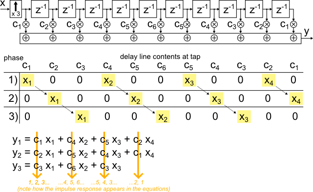
Figure 1: FIR interpolation and polyphase equations
Clearly there is no point in performing expensive multiplications with (non)-samples that are known to be zero (BUT: this is perfectly fine for Matlab coding, as long as it helps to keep things 'simple and stupid'. Usually it does).
The equations at the bottom of Figure 1 show only remaining terms, if products with zeros are omitted.
The three output samples y1, y2 and y3 are calculated for each input sample (the x before zero insertion), as the interpolating FIR produces three output samples per input sample.
Textbook polyphase FIR interpolator
Instead of inserting zeros and then carefully multiplying around them, the structure can be rewritten using "slower" delays z-3 at the input rate (=> zzz => the sample goes to sleep for a while. Ahem.).
Now three output samples are generated for each step of the delay line, as shown in Figure 2:
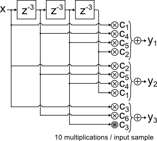
Figure 2: Conventional tapped delay-line implementation\
'FIR sideways':An alternative implementation
So far so good.
The implementation in Figure 2 is maybe the most common way to implement such a filter.
But, there is an alternative:
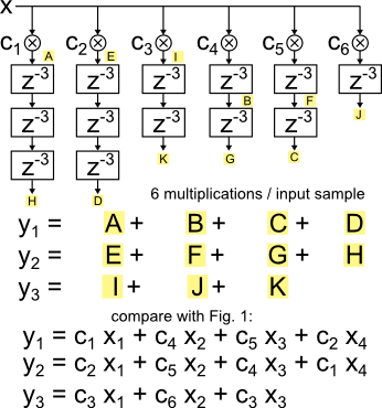
Figure 3: Alternative implementation
Figure 3 uses individual delay lines for each coefficient. The structure can always be implemented using one multiplication per independent coefficient and input sample.
The number of multiplications has been reduced from 10 to 6. And if the center tap can be fixed to 1, as is common, it improves from 9 to 5, which is even better.
Conclusion
This article shows a polyphase FIR interpolator for symmetric impulse responses that uses fewer multiplications than the textbook 'single-delay-line' implementation, in the example only two per output sample.
Does it make sense? Possibly "yes", justified by the application-dependent cost of multiplications.
In real life, "cost" is rarely as straightforward, but it may be worth having a look at.
For example, [1] (Fig 2.4) shows an application where a "non-canonical" polyphase structure can be beneficial.
Possible savings differ, depending on interpolation factor and filter length.
Matlab demo
The Matlab / Octave example calculates the filter response using the three methods outlined in this article.
The resulting plot (Fig. 4) shows the output, three identical and thus overlapping traces.
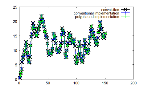
Figure 4: Matlab output
References


- Comments
- Write a Comment Select to add a comment


To post reply to a comment, click on the 'reply' button attached to each comment. To post a new comment (not a reply to a comment) check out the 'Write a Comment' tab at the top of the comments.
Please login (on the right) if you already have an account on this platform.
Otherwise, please use this form to register (free) an join one of the largest online community for Electrical/Embedded/DSP/FPGA/ML engineers:


