


'z' as in 'Zorro': Frequency Masking FIR
An efficient way to implement FIR filters. Matlab / Octave example included.
Keywords: Frequency masking FIR filter implementation
Introduction
An "upsampled" FIR filter uses multiple-sample delays between the taps, compared to the unity delays in a conventional FIR filter. The resulting frequency response has steeper edges, but contains periodic images along the frequency axis (Fig. 1).
Due to the latter, it is typically not too useful on its own.
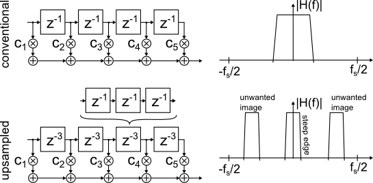
Figure 1: Conventional and 'upsampled' FIR
The so-called "interpolated" FIR, or "IFIR" [2] adds a second stage to remove unwanted frequency response images. For an example, see [3] Fig. 6 and 7, also [1] Fig. 2.
As one period of the upsampled FIR defines the width of the passband, this idea won't work for wideband filters.
Frequency Masking FIR filter
The "frequency masking FIR filter" [1] circumvents said problem and can achieve a steep transition at the edge of a wide bandwidth.
A complementary filter is constructed from the upsampled filter by subtracting its output from a unity impulse response with the same group delay (conveniently derived from the same tapped delay line at no extra cost).
Where the upsampled filter has a passband, the complementary filter shows a stopband, and vice versa.
Either filter output is highly frequency selective relative to the other, but no information is lost as a whole.
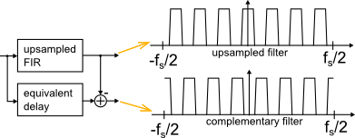
Figure 2: Upsampled and complementary FIR
Next, independent FIR filters g1 and g2 are added to the outputs, and the results are summed (Figure 3). This is the basic topology of the "frequency-masking FIR filter":
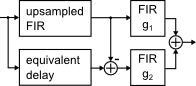
Figure 3: Frequency Masking FIR filter
Design process
So far so good. Assuming that it worked (which seemed a bit dubious, at least to me), how on earth would I design such a thing?
A systematic approach that seems to be best suited for very long filters can be found in [1] and [4].
After studying it for an hour, I remembered the old chinese proverb: If fminunc() doesn't know the answer, you're asking the wrong questions.
Alright, I just made this up, but the "general purpose heavy-duty" solver does find a good answer after a minute-and-a-half (freeware OctaveForge; Matlab is about four times faster).
Note that this gives a least-squares solution, whereas the original design in [1] is minimax-constrained. If the latter is needed, use of IRLS techniques to adjust the weights should be straightforward.
Slowly ramping up the order of the norm in the objective function during iteration is another method that has been successfully used to "nudge" a LS-design slightly towards minimax with little effort.
Result
The following plots are generated by the attached Matlab program. They show the frequency responses of individual stages (Fig. 4) and the input-output frequency response (Fig. 5).
It is interesting to note that the roles of the invividual stages in the least-squares-type solution only loosely resemble the "systematic" design approach in [1] and [4]!
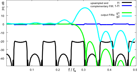
Figure 4: Frequency response (individual stages)
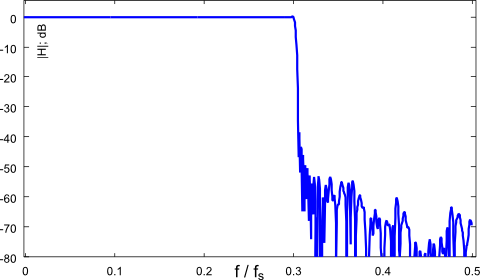
Figure 5: Frequency response (input-output): The complete wide-band filter
Performance
For comparison, the design script includes a conventional symmetric FIR filter as reference design.
It needs 401 non-zero taps, whereas the frequency masking FIR uses 45 + 33 + 41 = 119 taps.
Less than 1/3 of the computational load, not too bad, IMHO.
[1] reached a similar conclusion in section VII, giving 383 taps for a conventional FIR filter that meets the same specs. Note, "my" numbers show orders-of-magnitude only and aren't optimized carefully.
Matlab program
The design program can be downloaded here . It uses a generic solver with the difference between nominal and actual frequency response in the objective function.
From a practical perspective, the main difficulty is to juggle parameters and optimizer variables, making sure each coefficient ends up in the right slot of a filter's impulse response.
The oh_xyz "optimization helper" functions collect all optimization parameters from a struct into a single flat vector for the optimizer, and write the result back into the struct, which is then used to evaluate the frequency response.
Each filter's impulse response is constructed from a coefficient map as described in [5].
The purpose of all the "bureaucracy" is that changing the length ("delay") of each filter requires only a single modification to the code.
If one looks past all the (necessary) clutter, the program is maybe as straightforward as filter design ever gets:
- prepare the nominal frequency response and weights
- prepare the design frequency response
- prepare the objective function as weighted difference between above
- run the optimizer on the objective function
Summary
This article reviews the "frequency-masking FIR" concept from [1] and provides a "fire-and-forget" design program to explore the design space of filter sizes and oversampling factor.
References
[2] Ricardo A. Losada: Practical FIR Filter Design in Matlab
[3] Douglas A. Mann: Interpolated FIR (IFIR) Filters: A Case Study
[5] M. Nentwig: Weighted least-squares FIR with shared coefficients
Download
The program can be downloaded here .
It was developed on OctaveForge, and works on Matlab too (with toolboxes).


- Comments
- Write a Comment Select to add a comment
To post reply to a comment, click on the 'reply' button attached to each comment. To post a new comment (not a reply to a comment) check out the 'Write a Comment' tab at the top of the comments.
Please login (on the right) if you already have an account on this platform.
Otherwise, please use this form to register (free) an join one of the largest online community for Electrical/Embedded/DSP/FPGA/ML engineers:


