A brief look at multipath radio channels
Summary: |
Radio channels, their effects on communications links and how to model them are a popular topic on comp.dsp.
Unfortunately, for many of us there is little or no opportunity to get any "hands-on" experience with radio-related issues, because the required RF measurement equipment is not that easily available.
This article gives a very simple example of a radio link that shows multipath propagation and frequency-selective fading.
At my workplace I occasionally arrange mini lab-courses "RF for the DSP/software/... guys", and what follows is one of those experiments.
By the way, for the small number of readers that happen to work on the same site as I do: you are very welcome to try the experiment yourself, simply knock on my door if interested.
In a wireless link, the baseband signal is modulated to a radio frequency carrier. In comparison to the bandwidth at baseband, the carrier frequency is pretty high, for example 1 GHz. Due to its high frequency, the signal can be transmitted and received with a physically small antenna.
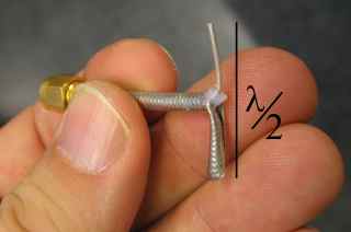
Such an antenna is shown below: It's a simple half-wave dipole for 4.5 GHz, made from a scrap piece of coaxial cable. Designing and tuning the antennas is by the way another good RF-related experiment that can be done using the same equipment.
The measurement instrument that I will use is a "network analyzer". It is a common work horse for the RF engineer:
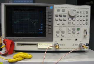
It has two connectors (ports). The instrument provides a radio-frequency signal at the first port, which will be connected to the first antenna.
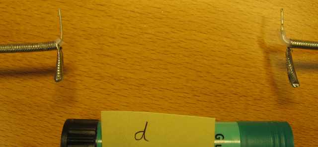
The RF signal is radiated from the first antenna. It is picked up by the 2nd antenna, connected to the 2nd port of the network analyzer
Here is the "radio link". Since this is not a precision measurement, the table surface makes no difference:
The instrument determines the relative amount of power that passes from port 1 to port 2. Further, it continuously sweeps the frequency and plots the magnitude of the frequency response.
The screenshot showing the result follows in the next section.
If the antennas were replaced by a cable, it would ideally report 0 dB for all frequencies, meaning that all power generated at port 1 is accounted for at port 2.
With the radio link it always shows a negative number of dBs, the path loss.
Path loss:
The second antenna will pick up only a small fraction of the power radiated from the first antenna, depending on the distance. Assuming that air is lossless, the radiated power is spread over the surface of a sphere which increases with the square of the distance (according to the so-called "inverse square law of electromagnetics").
This is easily demonstrated by doubling the distance between antennas:

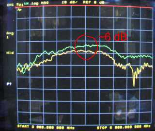
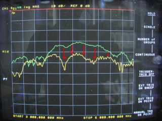
The screenshot below shows the measured frequency response of the link at distances d (upper curve, green), and 2d (lower curve, yellow).
Each grid division (on the vertical axis) corresponds to 10 dB. As expected, doubling the distance increases the path loss by roughly 6 dB, equivalent to a power difference by a factor of four:
Good to remember:
In free space, doubling the distance between antennas increases the path loss by 6 dB. In reality the loss is often higher, because the path dissipates power. If reflections occur, the resulting loss can be lower.
In a link level simulation, a channel model represents the radio path. Usually, the model for a time-varying channel is normalized to 0 dB: At some times it causes loss, at other times its gain is greater than unity. In the long-term average, the power of the signal remains as is.
A real radio link shows similar fluctuations - if the model is accurate - but has a high "base" attenuation, for example 50 dB or more.
Line-of-sight and multipath channel
The discussed radio path is a line-of-sight connection.
Putting an obstacle between the antennas interrupts the link.
Here, my thumb (well trained as a wideband RF terminator) blocks the line-of-sight connection:

As a result, the path loss increases drastically:
Still, there is plenty of signal energy, caused by reflections that bypass the obstacle (closer investigation reveals: mostly from the nearby table lamp)
Multipath channels
Designing a communication system for line-of-sight connections is difficult enough.
Examples are:
- directional radio links ("dish antennas")
- satellite communications
- GPS, which, by the way, does not "like" reflections at all!
Now most ground-based wireless devices are expected to operate in the absence of a line-of-sight component. This is one of the key challenges in wireless systems design, namely to exploit the signal energy from reflections and to mitigate fading.
Due to the high frequency of the RF signal, the wavelength is rather short:
In the example using 4.5 GHz, it is 6.5 cm. Therefore, a small piece of sheet metal held next to the antennas works fine as reflector:
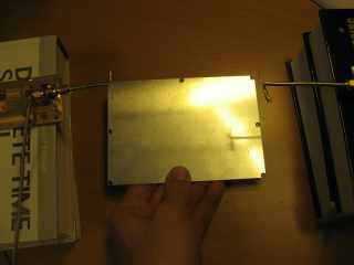
Below the effect on the frequency response, and this is where it starts to get interesting with an eye towards digital signal processing.
I have repeated the measurement three times, holding the metal reflector at slightly different height: A notch is clearly visible, and it moves to higher frequencies, when I shorten the path length of the reflection by raising the plate.
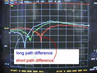
Why is there a "notch"? It's simple:
Consider the blue curve, where the notch appears at 3.5 GHz. The corresponding wavelength is 8.5 cm. Comparing the direct path and the reflected path, it turns out that the difference is half a wavelength, a little bit more than 4 cm.
The latter delays the signal by half a cycle length, compared to the direct path.
The two signals sum up at the receiving antenna. They have (almost) equal amplitude and opposite phase, therefore they cancel each other. The notch in the frequency response results.
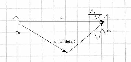
"footnote": The reflection itself may cause a sign change, but it doesn't really matter here.
When raising the reflector closer to the antennas, the absolute path difference shortens. The wavelength that fits half a cycle into the path difference becomes smaller, and the notch shifts to higher frequencies.
So what we have here is frequency-selective fading caused by multipath propagation.
Frequency selective or flat fading?
The network analyzer screenshots shows a wide bandwidth - 3 GHz to 6 GHz.
However, a typical communications signal has a much smaller bandwidth, for example up to 20 MHz for WLAN.
Below I have moved a marker to 3.85 GHz, close to the notch:
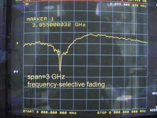
And here is exactly the same channel frequency response, but this time zoomed in to a 20 MHz bandwidth:
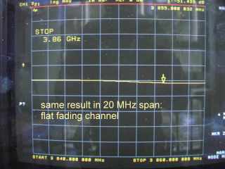
As it turns out, the channel is (almost) perfectly flat within a bandwidth of 20 MHz! In other words, as far as a 20 MHz wide signal is concerned, we've got almost a flat fading channel. It becomes frequency selective only for wanted signals of a much wider bandwidth.
In a link-level simulation, the channel model operates at a low sampling rate related to the bandwidth, not the center frequency. The channel model corresponding to the example above is a one-tap FIR filter, in other words, a constant gain factor.
For narrowband signals, multipath reflections on nanosecond time scale result in a complex gain factor, but practically no intersymbol interference.
This is one of the reasons for the attractiveness of OFDM: One may consider a wideband OFDM signal as a large number of independent narrowband signals. For each of them, the channel appears only as a flat fading channel, or in other words, a complex factor that is constant over the duration of the symbol.
Longer path difference
As a final example, I changed the reflected path length to several wavelengths (some "cheating" involved to balance the amplitudes): Now there are several frequencies where the path difference is n+1/2 (n being integer). Consequently, the frequency response shows periodic notches, and it starts to look like an actual radio channel:
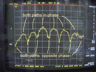
In reality, typical path length differences will be much higher, and there will be multiple reflections. It follows, that a typical 20 MHz channel in an office environment is highly frequency selective.
This is a major design challenge for a radio system. For example OFDM or SC-FDMA are attractive, because they allow channel estimation and equalization of the received signal using efficient frequency domain methods.
Conclusion
I hope that this article has been somewhat useful to shed some light on what the radio path does to our signals. Any comments and questions are of course appreciated.
Cheers
Markus
References: http://www.eecs.berkeley.edu/~dtse/Chapters_PDF/Fundamentals_Wireless_Communication_chapter2.pdf
Thanks to Rifat for this link.
- Comments
- Write a Comment Select to add a comment


Thanks for this article on frequency selectivity. Would you please shed some light on time selectivity of the channel (the Doppler bandwidth, how is it modelled when multiple paths have different angles of arrival and consequently different shifts, and finally how to handle/equalize the time-varying channel without assuming block fading models)? Thanks a lot.
To post reply to a comment, click on the 'reply' button attached to each comment. To post a new comment (not a reply to a comment) check out the 'Write a Comment' tab at the top of the comments.
Please login (on the right) if you already have an account on this platform.
Otherwise, please use this form to register (free) an join one of the largest online community for Electrical/Embedded/DSP/FPGA/ML engineers:


