Time Machine, Anyone?
Abstract: Dispersive linear systems with negative group delay have caused much confusion in the past. Some claim that they violate causality, others that they are the cause of superluminal tunneling. Can we really receive messages before they are sent? This article aims at pouring oil in the fire and causing yet more confusion :-).
Introduction
In this article we reproduce the results of a physical experiment [1] with an electronic circuit with negative group delay. In that experiment it was shown that pulses centered at a frequency in the range of the negative group delay looked like they emerged from the circuit before going in. After briefly reviewing group delay, we present the circuit and a simple second order discretization of the transfer function. This discrete filter is then used to repeat and extend the experiments with signals in the band of negative group delay. The article concludes with musings about the meaning of negative and positive group delay. Matlab code to generate the figures is appended for readers interested in pursuing the matter further.
Definition of Group Delay
The group delay of a linear time-invariant (LTI) system, from now on referred to as filter, is defined as the negative of the derivative of the phase response with respect to frequency. In formulas: Let H(j ω) be the frequency response function of the filter,
φ(ω) = arg( H(j ω) )
denote the phase response, then
τ(ω) = - dφ(ω)/dω
is the group delay. It is a function of the frequency ω and we colloquially say it is "'the time delay of the amplitude envelope of a sinusoid at frequency ω". To understand what "the time delay of the amplitude envelope" is, we think of a pulse p(t) that is modulated by a carrier sinusoid at frequency ω,
x(t) = p(t) cos(ω t).
If the group delay and the magnitude of the filter are reasonably flat around ω, the filter looks approximately like a delay in the neighborhood of ω, so the pulse shape (envelope) won't be influenced much. In that case we expect the output signal y(t) to approximately be
y(t) ~= |H(j ω)| p(t - τ(ω)) cos(ω t + φ(ω)). (1)
Looking at the waveform of input and output signals, the group delay can thus be measured by the time difference from the input pulse envelope peak to the output pulse envelope peak. In contrast, the sinusoid will be shifted by the amount dictated by the phase response of the filter at ω.
If you think you are confused, read how the experts bash in their heads about the physical meaning of group delay in this rather lengthy newsgroup discussion. A further source of puzzlement is the fact that some filters have bands of negative group delay. If we insist on the idea that the group delay is a measure of, well, delay, then negative group delay would imply that a signal can exit an electronic circuit before it enters it. Hmm. Let's take a closer look.
Example of a Filter with Negative Group Delay
In reference [1] a simple active filter is analyzed by the authors. Its circuit diagram is shown in Fig. 1.
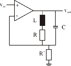
Fig. 1. Circuit diagram of the active filter at the heart of the
electronic negative group delay experiment described in [1].
The frequency response function of this filter is easily shown to be
H(j ω) = 1 + 1/R' 1/( (R + j ω L)-1 + j ω C).
If we plug in the values R=3 kΩ, L= 100 H, C= 0.098 μF and R'= 30 kΩ, we see that the circuit behaves like a high-Q peaking filter with a resonance at fr = 1/(2 π) sqrt(1/LC - (R/2L)^2) ≈ 51 Hz (blue curve in Fig.2 shows the frequency response of H(j ω)). Any electronics practitioner will readily testify that the circuit from Fig. 1 is causal, meaning that the output cannot anticipate the input. Other people compute the impulse response and note that the impulse response is zero for t < 0.
We will now proceed to find a discrete filter with comparable characteristics in order to be able to reproduce the experiment in Matlab world. To discretize this filter we use Greg Berchin's FDLS method [3], which is available as a Matlab script. Using a logarithmic spaced frequency vector sampling 400 points of H(j ω) from 1 up to 1000 Hz and a sampling rate of Fs = 4kHz, we get the following biquad section: 1.0770389918072 - 2.03115724017531 z-1 + 0.961079950480885 z-2
Hd(z) = ------------------------------------------------------------- (2)
1 - 1.98606828810359 z-1 + 0.992414110487639 z-2
The approximation is not perfect (the red curve in Fig. 2 depicts the frequency response of the discrete filter), but will serve for this little experiment.
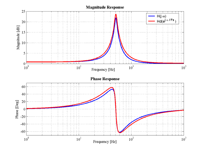
Fig. 2. Bode plot (blue: analog filter depicted in Fig. 1, red: discrete approximation (2)). The discretized filter Hd(z) has slightly wider bandwidth than its analog counterpart H(j w), but else captures the characteristics of the analog filter. Both filters have minimum-phase responses, implying that there are stable and causal inverses.
Inspecting the curve of the phase response of the filter in Fig. 2, we see that there are regions where the group delay is negative. Specifically, everywhere where the phase response curve slopes upwards the group delay is negative. In fact, as can be seen in the group delay plots in Fig. 3, the only band where the group delay of this filter is not negative is in the relatively small resonance region around fr ≈ 51 Hz.
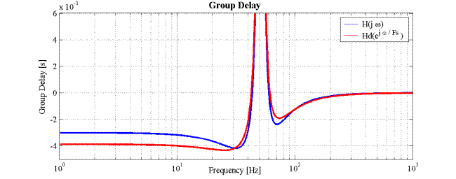
Fig. 3. The group delay for both the analog and the discrete system is negative except in a small band around the resonance frequency. As a beneficial but unintentional discretization side-effect, the discretized filter Hd(z) has about 1ms less group delay than the analog filter H(j ω) for low frequencies.
The Experiment
The original experimenters cascaded the circuit shown in Fig. 1 four fold to produce an extremely resonant filter with around 90dB of gain in the resonance region. The test signal p(t) is a modulated Gaussian pulse centered at t = 0 with a width of σ seconds,
p(t) = exp(-(t / σ)2) .
The pulse width σ=25 ms is chosen to be in the order of the group delay of the filter to be able to better see the effect of the group delay. This pulse is next modulated with two different carriers and then passed through the cascaded filters. First, we apply a signal x1(t) to the cascaded filter with a carrier frequency of f1 = 100 Hz, ie.
x1(t) = p(t) cos(2 π f1 t),
resulting in the output signal y1(t).
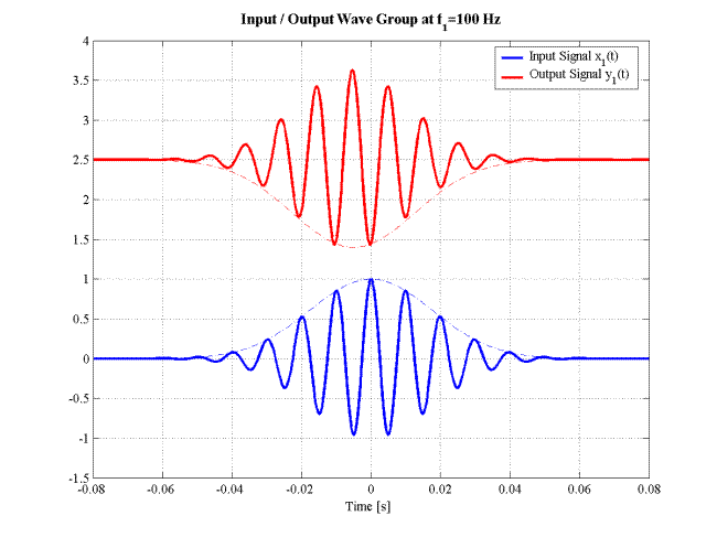
Fig. 4. Input x1(t) and output signal y1(t), with appropriately scaled and shifted Gaussian envelopes suggested in dashed lines (note how the envelope does not quite fit the output signal, indicating that (1) is just an approximation). The output signal y1(t) is offset and scaled by |Hd(j 2 π f1)|-4 for display. The peak of the output signal appears 5ms before the peak of the input signal. This corresponds well with the theoretical value of -1.2ms group delay of the single filter section at f1=100 Hz (see Fig. 3).
Looking at Fig. 4 we see that the heuristic (1) to predict the response of a filter to a wave group (carrier modulated pulse) is quite good. The group delay at f1 = 100 Hz of the filter is -1.2ms which results in a total of -5ms delay after four runs through the filter, and the amplitudes of input signal and output signal scaled by |Hd(j 2 π f1)|-4 match up to an error of about 10%.
At low frequencies the negative delay effect should be even more pronounced, because according to Fig. 3 the group delay at low frequencies is about -4ms, so we expect the cascade of four filters to have a combined group delay of about -16ms. To test this we modulate the Gaussian pulse p(t) by a sinusoid at frequency f2 = 1 Hz, creating the input signal
x2(t) = p(t) cos(2 π f2 t),
and the corresponding output y2(t), seen in Fig. 5.
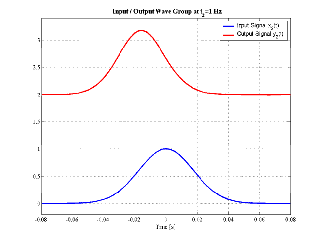
Fig. 5. Input x2(t) and output signal y2(t) at f2 = 1 Hz carrier frequency. The output is scaled by the gain of the filter at f2 and offset by 2.5. Again, the output precedes the input by the group delay at the carrier frequency, which is 16ms. This nice example shows that measuring the speed of propagation of wave packets by measuring the time difference between the peaks may be misleading.
Inspecting the frequency response in Fig. 2. once more, we note that the magnitude response of the filter is more or less flat from 0 - 10 Hz, whereas the phase response "leads" (is positive). The group delay (Fig. 3.) shows that the phase lead has a constant slope. Thus in the band from 0 - 10 Hz the circuit has (almost) the same frequency response as the corresponding acausal time advance of 4ms. Physicists like to experiment with pulses, but in DSP we like stochastic signals. So in addition to the experiments with the pulses conducted in [1] and repeated above, we check the response for a random bandlimited signal to test if the circuit behaves like a time advance for more complex signals as well as for pulses. The test signal will be
x4(t) = hLP(t) * u(t)
where hLP(t) is the impulse response of a 10Hz lowpass filter (remember the sampling frequency Fs = 4kHz), * denotes convolution and u(t) is a sequence of independent standard normal random numbers. This test signal and the corresponding filter response are shown in Fig. 6. The uncanny result is that even for random signals, the filter time advances the input by the group delay, verifying the result of the pulse experiments.
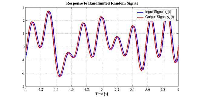
Fig. 6. The response y4(t) to a bandlimited random signal x4(t) is even more baffling. The filter predicts the input 16ms into the future (and doesn't make much error doing so). Note the different time scale as compared to the other figures. The signal x4(t) is generated by sinc-interpolation (upsampling) of a white noise signal.
All of these experiments lead us to doubt the causality of the filter, even though the impulse response clearly satisfies the conditions for a causal filter (being zero for negative time). So in the final experiment we aim to "trick" the filter. We repeat the experiment depicted in Fig. 5, however, this time the pulse p(t) will be truncated at t=0 (see Fig. 7). 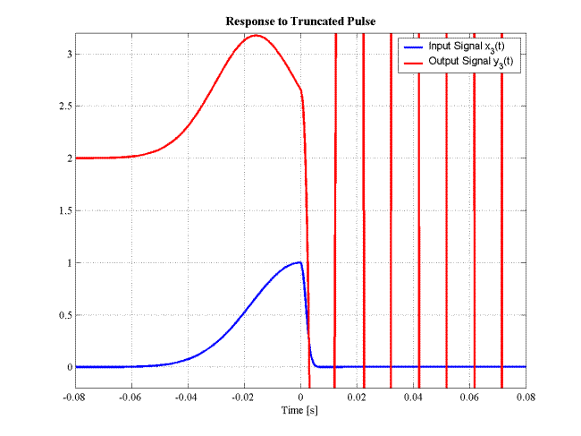
Fig. 7. The response of the filter to the truncated pulse input signal x3(t) shows that the filter behaves causal. The truncation of the input at the pulse peak does not occur at the pulse peak in the output signal y3(t), rather it is an instantaneous response to the truncation of the input signal in the output signal. The high frequency content of the truncation excites the resonance of the filter, resulting in extremely amplified 51Hz trail after the truncation.
As can be seen in Fig. 7., the filter first predicted the pulse to be symmetric. When the truncation of the pulse sets in, the filter immediately reacts to the unpredictable event in a causal manner. The large oscillation is excited by the frequency content of the pulse truncation in the resonance region.
After these enlightening experiments, what can we conclude about causal negative group delay systems?
Physical Meaning of Negative Group Delay?
So what exactly is the physical meaning of negative group delay? For positive delays, the meaning seems clear and can readily be expressed through (1). The envelope of the carrier signal is delayed by the group delay. However, negative group delays do not imply time advance (at least not in causal systems). Rather, for signals in the band where the group delay is negative the filter tries to predict the input. If the signal is predictable from past values (as for the modulated Gaussian pulse and the bandlimited random signal, Figs. 4,5,6), then this brings about the illusion of a time advance. The illusion breaks down when the signal contains an unpredictable event (the truncation of the Gaussian pulse, Fig. 7).
But what signals are predictable? In the above example, the illusion of time advance only works if the signal is limited to the band where the group delay is negative (and the amplitude response is relatively flat). It is well known that bandlimited signals are redundant. Discrete oversampled signals carry more samples than are necessary to describe them. It can be shown (see for example [4]) that signals oversampled by a factor of 2 (or more) can be fully reconstructed from just the past samples up to time t=0 by using a linear prediction filter. And exactly this is occurring here: the test signals are contained in narrow bands and therefore highly redundant. The filter uses this redundancy to predict the signal (linear prediction filter). In the continuous-time domain, the situation is even more dramatic: a bandlimited signal can theoretically be reconstructed from just knowing its value over a small stretch of time (this is called analytic continuation). Thus knowledge of the past is sufficient to predict the future (remember, theoretically).
We hope to have entertained the reader with this excursion into causal negative group delay filters. Matlab code to generate the figures in this text is appended below. For more detailed analysis of negative group delay in electronic systems and some more simple examples of electronic circuits with negative group delay the reader may refer to [1] or [2].Matlab Code
% Matlab program used to generate the figures for the article
% "Time Machine, Anyone?", published March 7. 2008 on
% http://www.dsprelated.com/blogs.php
%
% Copyright 2008, Andor Bariska.
% This program is free software: you can redistribute it and/or modify
% it under the terms of the GNU General Public License as published by
% the Free Software Foundation, either version 3 of the License, or
% (at your option) any later version.
%
% This program is distributed in the hope that it will be useful,
% but WITHOUT ANY WARRANTY; without even the implied warranty of
% MERCHANTABILITY or FITNESS FOR A PARTICULAR PURPOSE. See the
% GNU General Public License for more details.
%
% A copy of the GNU General Public License is available from
% http://www.gnu.org/licenses/.
% Sample transfer function H:
n=400;
f=logspace(log10(1),log10(1000),n); % sample with logarithmic frequency scale
w=2*pi*f;
R=3000; L=100; C=0.098e-6; Rd=30000;
H=1 + 1/Rd*1./( (R+i*w*L).^-1 + i*w*C);
% Creat Bode plot of transfer function H:
figure(1); subplot(2,1,1)
semilogx(f,20*log10(abs(H)))
xlabel('Frequency [Hz]','FontName','Times')
ylabel('Magnitude [dB]','FontName','Times')
title('Magnitude Response','FontName','Times','FontSize',12,'FontWeight','bold')
grid on
subplot(2,1,2)
semilogx(f,180/pi*angle(H))
xlabel('Frequency [Hz]','FontName','Times')
ylabel('Phase [Deg]','FontName','Times')
title('Phase Response','FontName','Times','FontSize',12,'FontWeight','bold')
axis([1 1000 -70 70])
grid on
% Prepare design matrix M used by FDLS:
Fs = 4000; % sampling rate for digital system
M=[f' abs(H)' 180/pi*angle(H)' ones(n,1)]; % Design matrix for FDLS
fid = fopen('dm.dat','w');
fprintf(fid, '%u %u \n', n, Fs); % write header (number of data points and sampling rate)
fprintf(fid, '%12.8e %12.8e %12.8e %12.8e \n', M'); % write frequency response data
fclose(fid);
FDLS_200 % Calls FDLS script, filter coefficients returned in B (num) and A (denom).
% Here is the prompted dialogue with the script:
%
% Enter name of input file: dm.dat
% M =
%
% 400
%
%
% samplerate =
%
% 4000
% Enter numerator order "N": 2
%
% N =
%
% 2
%
% Enter denominator order "D": 2
%
% D =
%
% 2
%
% Enter artificial delay (number of samples): 0
% delta =
%
% 0
%
%
% Working ...
%
% B =
%
% 1.0770389918072
% -2.03115724017531
% 0.961079950480885
%
%
% A =
%
% 1
% -1.98606828810359
% 0.992414110487639
% plot impulse response:
tend = 0.2; t=0:1/Fs:tend; % plot impulse response up to time "tend"
g=R/(2*L); wr=sqrt(1/(L*C)-R^2/(4*L^2));
h=exp(-g*t)/(Rd*C).*(cos(wr*t)+R/(2*L*wr)*sin(wr*t)); % impulse response of analog filter
hd=filter(B,A,[1 zeros(1,tend*Fs)]); % impulse response of discrete filter
figure(9);
hold off
plot(t,hd*Fs,'r.')
hold on
plot(t,h,'b','LineWidth',2)
axis([0 tend -400 450])
xlabel('Time [s]','FontName','Times')
title('Impulse Responses','FontName','Times','FontSize',13,'FontWeight','bold')
legend('Discrete Filter','Analog Filter');
grid on
% compute frequency response of Hd(w):
z=exp(i*w/Fs); zM =[ones(1,n); z.^(-1); z.^(-2)];
Hdw=(B'*zM)./(A'*zM);
% plot frequency response:
figure(1); subplot(2,1,1)
hold on
semilogx(f,20*log10(abs(Hdw)),'r')
legend('H(j \omega)','Hd(e^{j \omega / Fs })');
subplot(2,1,2)
hold on
semilogx(f,180/pi*angle(Hdw), 'r')
% compare frequence response with 4ms time advance:
Oneto10hz=1:134; g1hz=20*log10(abs(Hdw(1)));
figure(6); subplot(2,1,1)
semilogx(f(Oneto10hz),20*log10(abs(Hdw(Oneto10hz)))-g1hz,'r',f(Oneto10hz),20*log10(abs(exp(2*pi*i*f
(Oneto10hz)/Fs*16))),'g')
xlabel('Frequency [Hz]','FontName','Times')
axis([1 10 -1 1])
subplot(2,1,2)
semilogx(f(Oneto10hz),180/pi*angle(Hdw(Oneto10hz)), 'r',f(Oneto10hz),180/pi*angle(exp(2*pi*i*f
(Oneto10hz)/Fs*16)),'g')
xlabel('Frequency [Hz]','FontName','Times')
% plot group delay:
figure(2);
dpH = diff(angle(H))./diff(w);
semilogx(f(2:end),-dpH)
hold on
dpHdw = diff(angle(Hdw))./diff(w);
semilogx(f(2:end),-dpHdw,'r')
title('Group Delay','FontName','Times','FontSize',12,'FontWeight','bold');
xlabel('Frequency [Hz]','FontName','Times')
ylabel('Group Delay [s]','FontName','Times')
legend('H(j \omega)','Hd(e^{j \omga / Fs })');
axis([1 1000 -5.e-3 6e-3])
grid on
% run the modulated exponential pulse through filter:
tmin=-0.15; tmax=.15; % time boundaries
t=tmin:1/Fs:tmax;
tau=25e-3; % Gaussian pulse width
p=exp(-(t/tau).^2); % definition of Gaussian pulse
t0 = find(t>=0);
p2=[exp(-(t(1:t0(1))/tau).^2) exp(-(t(t0(1)+1:end)/(.1*tau)).^2)]; % A pulse consisting of a wide half for
negative time and a narrow half for positive time
f1=100;
x1=p.*cos(2*pi*f1*t); % input signal x1
f2=1;
x2=p.*cos(2*pi*f2*t); % input signal x2
x3=p2.*cos(2*pi*f2*t); % input signal x3
socascade = [B' A';B' A';B' A';B' A'];
f1ind = find(f >= f1);
y1=1/abs(Hdw(f1ind(1)))^4*sosfilt(socascade,x1); % output signal y1=Hd[x1]
f2ind = find(f >= f2);
y2=1/abs(Hdw(f2ind(1)))^4*sosfilt(socascade,x2); % output signal y2=Hd[x2]
y3=1/abs(Hdw(f2ind(1)))^4*sosfilt(socascade,x3); % output signal y3=Hd[x3]
tpmin=-0.08; tpmax=0.08;
figure(3);
hold off
plot(t,x1,'b','LineWidth',2)
hold on
plot(t,y1+2.5,'r','LineWidth',2)
plot(t,p,'b-.',t-0.005,-1.1*p+2.5,'r-.')
axis([tpmin tpmax -1.5 4.])
xlabel('Time [s]','FontName','Times')
title('Input / Output Wave Group at f_1=100 Hz','FontName','Times','FontSize',13,'FontWeight','bold')
legend('Input Signal x_1(t)','Output Signal y_1(t)');
grid on
figure(4);
hold off
plot(t,x2,'b','LineWidth',2)
hold on
plot(t,y2+2,'r','LineWidth',2)
axis([tpmin tpmax -.2 3.4])
xlabel('Time [s]','FontName','Times')
title('Input / Output Wave Group at f_2=1 Hz','FontName','Times','FontSize',12,'FontWeight','bold')
legend('Input Signal x_2(t)','Output Signal y_2(t)');
grid on
figure(5);
hold off
plot(t,x3,'b','LineWidth',2)
hold on
plot(t,y3+2,'r','LineWidth',2)
xlabel('Time [s]','FontName','Times')
title('Response to Truncated Pulse','FontName','Times','FontSize',12,'FontWeight','bold')
legend('Input Signal x_3(t)','Output Signal y_3(t)');
axis([tpmin tpmax -.2 3.2])
grid on
% time advance random signal:
x4=bandlimsig(20000,pi*(1-10/4000)); % generate a random signal bandlimited to 10 Hz @ 4000 Hz Fs.
y4=1/abs(Hdw(1))^4*sosfilt(socascade,x4); % output signal y4=Hd[x4]
t4=1/Fs*(0:length(x4)-1);
figure(7);
plot(t4,x4,'b','LineWidth',2)
hold on
plot(t4,y4,'r','LineWidth',2)
xlabel('Time [s]','FontName','Times')
title('Response to Bandlimited Random Signal','FontName','Times','FontSize',12,'FontWeight','bold')
legend('Input Signal x_4(t)','Output Signal y_4(t)');
axis([4 6 -3 3])
grid on
function x = bandlimsig(N,e)
% Generate 2N+1 samples of a (pi-e)-bandlimited random signal.
f = (pi-e)/pi; % bandlimit fraction
M = ceil(f*N); % 2*M+1=number of full band samples
r = randn(2*M+1,1); % white standard normal signal
x = zeros(2*N+1,1); % initialize with zero-vector
for k=(-N):1:N
 sincvec=sinc(k*(pi-e)/pi-((-M):1:M)');
 x(k+N+1)=dot(r,sincvec);
end
References
[1] M. W. Mitchell, R. Y. Chiao, Negative group delay and "fronts" in a causal system: An experiment with very low frequency bandpass amplifiers, Physics Letters A 230, 133-138, June 1997.
[2] M. Kitano, T. Nakanishi, and K. Sugiyama, Negative Group Delay and Superluminal Propagation: An Electronic Circuit Approach, http://arxiv.org/PS_cache/quant-ph/pdfneighborhood/0302/0302166v1.pdf
[3] G. Berchin, Precise Filter Design, DSP Tips & Tricks, Signal Processing Magazine, 24, 137-139, January 2007. http://apollo.ee.columbia.edu/spm/external/tipsandtricks/files/TandT_Jan2007.zip
[4] S.R. Pillai, B. Elliott, New results on the reconstruction of bandlimited signals from past samples, Electronics Letters , 29, 1501-1503, Aug 1993.
Copyright © 2008, Andor Bariska. All Rights Reserved.
- Comments
- Write a Comment Select to add a comment


To post reply to a comment, click on the 'reply' button attached to each comment. To post a new comment (not a reply to a comment) check out the 'Write a Comment' tab at the top of the comments.
Please login (on the right) if you already have an account on this platform.
Otherwise, please use this form to register (free) an join one of the largest online community for Electrical/Embedded/DSP/FPGA/ML engineers:


