


Linear-phase DC Removal Filter
This blog describes several DC removal networks that might be of interest to the dsprelated.com readers.
Back in August 2007 there was a thread on the comp.dsp newsgroup concerning the process of removing the DC (zero Hz) component from a time-domain sequence [1]. Discussed in that thread was the notion of removing a signal's DC bias by subtracting the signal's moving average from that signal, as shown in Figure 1(a).

Figure 1.
At first I thought such a DC removal scheme would have the very poor passband peak-peak ripple performance of roughly 13 dB because of the 13 dB stopband ripple of a moving averager. But upon modeling this DC removal scheme I found that its passband behavior was better than I had expected. My modeling involved a computationally efficient D-point moving averager (MA), shown in Figure 1(b). The bottom path, in Figure 1(b), is a simple delay line having a length equal to the averager's group delay, (D-1)/2 samples. This enables us to time-synchronize the averager's v[n] output with the x[n] input in preparation for the subtraction operation.
The D-point moving averager (MA) in Figure 1(b) has a transfer function defined by

The second ratio in Eq. (1) is merely a recursive running sum comprising a D-length comb filter followed by a digital integrator. There are two delay lines in Figure 1(b); the bottom path's (D-1)/2 length delay, and the comb subfilter's delay line of length D within the MA.
This DC removal network's passband performance, when D = 31, is shown in Figure 1(c). (The frequency axis value of 0.5 corresponds to a cyclic frequency of half the input signal's Fs sample rate.) While the network has the desired infinite attenuation at zero Hz, its passband peak-peak ripple is unpleasantly large at 2.9 dB. We can do better, as we shall see.
If D is an integer power of two the 1/D scaling in (1) can be performed using a binary right shift by log2(D) bits, making Figure 1(b) a multiplier-free network. However, in that scenario the MA's group delay is not an integer number of samples, making it difficult to synchronize the delayed x[n] and the v[n] sequences. To solve this problem we can use two cascaded D-point MAs as shown in Figure 2(a). Because the cascaded MAs have an integer group delay of D-1 samples, we can be clever and tap off the first moving averager's comb delay line eliminating the bottom-path delay line in Figure 1(b). This way we still only need implement two delay lines in Figure 2(a), one delay line for the comb subfilter in each MA.
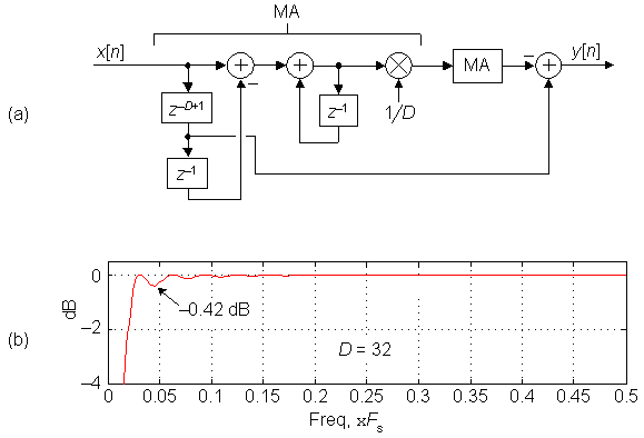
Figure 2.
The magnitude response of the Figure 2(a) dual-MA DC removal network, for D = 32, is shown in Figure 2(b). In that figure we show the DC removal filter's passband with its narrower transition region width and a much improved peak-peak ripple of 0.42 dB. What we've created then is a linear-phase, multiplierless, DC removal network having a narrow transition region near zero Hz.
Happily, it's worth noting that standard tapped delay-line, linear phase, highpass FIR filter designs using least-squares error minimization, or the Parks-McClellan method, require more than one hundred taps to approximate our D = 32 DC removal filter's performance.
On a practical note, the MAs in Figure 2(a) contain integrators that can experience data overflow. (An integrator's gain is infinite at DC.) Using two's complement fixed-point arithmetic avoids integrator overflow errors if we ensure that the integrator (accumulator) bit width is at least:

where q[n] is the input sequence to an accumulator, and ékù means: if k is not an integer, round it up to the next larger integer.
For an even narrower transition region width, in the vicinity of zero Hz, than that shown in Figure 2(b), we can set D to a larger integer power of two, however this will not reduce the DC removal network's passband ripple.
At the expense of three additional delay lines, and four new addition operations per output sample, we can implement the linear phase DC removal filter shown in Figure 3(a). That quad-MA implementation, having a group delay of 2D-2 samples, yields an improved passband peak-peak ripple of only 0.02 dB, as shown in Figure 3(b), as well as a reduced-width transition region relative to the dual-MA implementation.
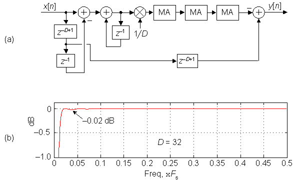
Figure 3.
The frequency magnitude responses of the Figure 3(a) network, for several values of D, are shown in Figure 4.
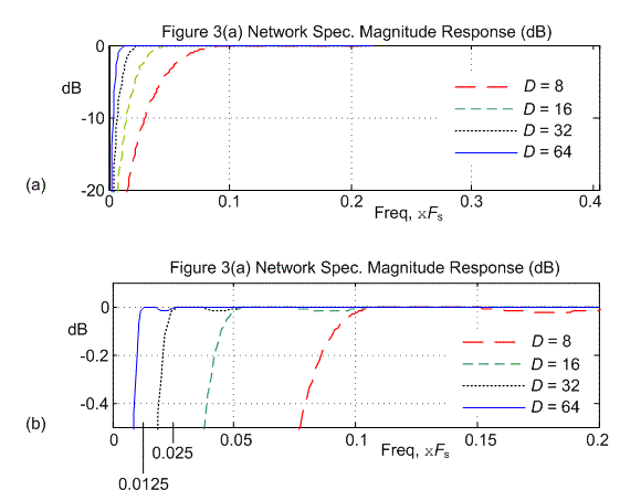
Figure 4.
So the bottom line to this blog is: At the expense of multiple delay lines, it is possible to perform efficient (multiplier-free) linear-phase DC removal.
[1] Posts during July 31 - August 8, 2007, Subject: "Regarding DC removal filter".


- Comments
- Write a Comment Select to add a comment
can you please send me a matlab code of above article

Ahmad1990, here is some MATLAB code for you to work with:
% Filename: DC_Removal_for_distribution.m
%
% Models the " DC Removal" scheme using cascaded
% recursive running sum (RRS) filters and subtracting
% the filter's output from a delayed version of the input.
% Models single-stage, 2-stage, and 4-stage RRS filters.
% Richard Lyons, April, 2018
clear, clc
% Set the desired delay line length
D = 31 % WARNING!! For a 1-stage DC blocker 'D' must be an odd number.
%%%%%%%%%%%%%%%%%%%%%%%%%%%%%%%%%%%%%%%%%%%%%%%%%
% Design 1-, 2-, & 4-stage lowpass RRS (moving averaging) filters
%%%%%%%%%%%%%%%%%%%%%%%%%%%%%%%%%%%%%%%%%%%%%%%%
B_1Stage = (1/D)*[1, zeros(1,D-1), -1]; A_1Stage = [1, -1];
B_2Stage = conv(B_1Stage, B_1Stage); A_2Stage = conv(A_1Stage, A_1Stage);
B_4Stage = conv(B_2Stage, B_2Stage); A_4Stage = conv(A_2Stage, A_2Stage);
%%%%%%%%%%%%%%%%%%%%%%%%%%%%%%%%%%%%%%%%%%%%%%%%%%%%%%%
% Add or delete the appropriate percent signs (%) in front of
% 'B_filter' variables to choose the number of deired RSS
% stages (single-, two-, or four-)
%%%%%%%%%%%%%%%%%%%%%%%%%%%%%%%%%%%%%%%%%%%%%%%%%%%%%%%
% Implement single-stage RSS
%B_filter = B_1Stage; A_filter = A_1Stage; B_delay_line = [zeros(1, (D-1)/2), 1]'; Order = 1;
% Implement two-stage RSS
B_filter = B_2Stage; A_filter = A_2Stage; B_delay_line = [zeros(1, D-1), 1]'; Order = 2;
% Implement four-stage RSS
%B_filter = B_4Stage; A_filter = A_4Stage; B_delay_line = [zeros(1, 2*D-2), 1]'; Order = 4;
%%%%%%%%%%%%%%%%%%%%%%%%%%%%%%%%%%%%%%%%%%%%%%%%%%%%%%%
% Analyze freq-domain performance of the DC-removal filter
%%%%%%%%%%%%%%%%%%%%%%%%%%%%%%%%%%%%%%%%%%%%%%%%%%%%%%%
[ImpRespFilter,T] = impz(B_filter, A_filter, 4*D+10);
[ImpRespDelay,T] = impz(B_delay_line, 1, 4*D+10);
ImpResp_DC_Remove_Filter = ImpRespDelay -ImpRespFilter;
H_Spec_mag = abs(fft(ImpResp_DC_Remove_Filter, 1024));
H_Spec_mag_dB = 20*log10(H_Spec_mag/max(H_Spec_mag));
%H_Spec_mag_dB = thresh(H_Spec_mag_dB, Threshold); % For plotting
FreqAxis = (0:1023)/(1024);
figure(1), clf
subplot(3,1,1), plot(FreqAxis, H_Spec_mag,'-r')
axis([0, 0.5, 0, 1.1])
title('FFT mag. of cascaded imp. responses')
ylabel('Linear'), grid on, zoom on
subplot(3,1,2), plot(FreqAxis, H_Spec_mag_dB,'-r')
axis([0, 0.5, -30, 2])
ylabel('dB'), grid on, zoom on
subplot(3,1,3), plot(FreqAxis, H_Spec_mag_dB,'-r')
axis([0, 0.2, -0.5, 0.1])
ylabel('dB'), xlabel('Freq (times Fs)'), grid on, zoom on
%%%%%%%%%%%%%%%%%%%%%%%%%%%%%%%%%%%%%%%%%%%%%%%%%%%%
% Compute & plot group delay to show phase linearity
%%%%%%%%%%%%%%%%%%%%%%%%%%%%%%%%%%%%%%%%%%%%%%%%%%%%
% Turn off warning when plotting group delay
warning off MATLAB:divideByZero,
[GD,W] = grpdelay(B_filter, A_filter, 1024, 'whole');
figure(2), clf
plot(W, GD,'-r', 'linewidth', 1)
ylabel('Group delay (samples)'), xlabel('Freq in rad./sample')
grid on, zoom on
Thanks a lot Mr.Rick Lyons.
If anyone have the Matlab C Converter, I would very much appreciate if they would post the C code here, thanks!

Hey I am doing a project on dc blocker and i need help!!
Project states:
Demonstrate any filter (FIR/IIR) with all parameter of filter .
DC blocker:
Steps:
- Choose a suitable Transfer Function suitable for the application
- Pass signal (x(n))
- Find output discrete /analog
- State which kind of filter (eg.FIR/IIR)
- Find out stability,PZ,side lobes ,transition band,order of the filter,attenuation
Please help!
Hello aditijoisher. I suggest your go to the following web page:
https://www.dsprelated.com/freebooks/filters/DC_Blocker.html#:~:text=The%20dc%20blocker%20is%20a%20small%20recursive%20filter,%28%29%20and%20a%20pole%20near%20dc%20at%20.
Implement the IIR filter described by the web page's Equation (B.10).
Analyze that IIR filter to answer all the questions in your above "Step# 5.
To post reply to a comment, click on the 'reply' button attached to each comment. To post a new comment (not a reply to a comment) check out the 'Write a Comment' tab at the top of the comments.
Please login (on the right) if you already have an account on this platform.
Otherwise, please use this form to register (free) an join one of the largest online community for Electrical/Embedded/DSP/FPGA/ML engineers:


