


The DFT Output and Its Dimensions
The Discrete Fourier Transform, or DFT, converts a signal from discrete time to discrete frequency. It is commonly implemented as and used as the Fast Fourier Transform (FFT). This article will attempt to clarify the format of the DFT output and how it is produced.
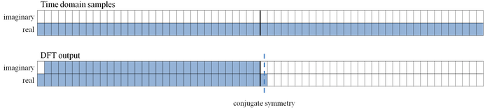
Living in the real world, we deal with real signals. The data we typically sample does not have an imaginary component. For example, the voltage sampled by a receiver is a real value at a particular point in time. Let’s say we take 64 samples spaced evenly over a period of one second. By the Nyquist sampling theorem, we can discern frequencies as high as 32Hz (assuming that we had previously low-pass filtered the input to avoid aliasing). The DFT produces as many output values as data points fed in, which would be 64 in this example. If we are looking at only 33 discrete integer frequencies (DC, 1Hz, 2Hz, …, 32Hz), then what are the other 31 values? Because the DFT output has conjugate symmetry when the input is real, the remaining 31 values are redundant.
All DFT outputs for a real N-sample input sequence with even N follow this pattern: 1 real value, N/2-1 complex values, 1 real value, N/2-1 conjugates. A diagram of the 64-point example is shown below, where blue squares indicate non-redundant information.
We started with 64 values and ended up with 33 non-redundant values after the DFT. What happened to the extra information? The DFT is invertible, so for every unique time-domain input sequence, there should be a unique DFT output. Because a real number has only one dimension and a complex number has two dimensions, the 64 real samples of the input occupy a total of 64 dimensions. From this input, the DFT produces 2 real values and 31 complex values, and the other 31 values returned by the DFT are just complex conjugates of the aforementioned complex values. If we look at the dimensions of the DFT result, we get 2+31*2 which is, again, 64 dimensions.
Let’s compute a 4-point DFT for clarification. Here is the formula for the DFT:
$$X_k=\sum_{n=0}^{N-1}x_ne^\frac{-j2\pi nk}{N}=\sum_{n=0}^{N-1}x_n\left(cos\left({\frac{2\pi nk}{N}}\right)-{j}sin\left(\frac{2\pi nk}{N}\right)\right)$$
Our input sequence is [$x_0$ $x_1$ $x_2$ $x_3$]. The formula above multiplies each sample of the input sequence by a corresponding sample in a complex exponential sequence. For a given value of n, the complex exponential sequence represents the linear combination of two sinusoids of the same frequency: one real and one imaginary. In essence, we are looking at the correlation of two sinusoids at each frequency with the input waveform. We have a 4-point DFT, so there are four frequencies of complex exponential sequences. We can stack these sequences by rows into a transformation matrix:
$$\left[\begin{matrix} X_0 \\ X_1 \\ X_2 \\ X_3 \end{matrix}\right] = \left[\begin{matrix} 1 & 1 & 1 & 1 \\ 1 & -j & -1 & j \\ 1 & -1 & 1 & -1 \\ 1 & j & -1 & -j \end{matrix}\right] \left[\begin{matrix} x_0 \\ x_1 \\ x_2 \\ x_3 \end{matrix}\right]$$
Here is a visual representation of the matrix elements using the complex unit circle:
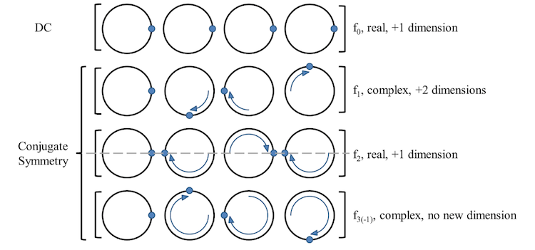
The first row is the DC component or the bias. It only has real components.
The second row is a single 4-point cycle around the complex unit circle, and it has imaginary components.
The third row is the only other row that has only real components. It is the highest frequency that can be sampled using four points (i.e. two cycles).
The fourth row is the complex conjugate of the second row. Observe how the points on the circle of the fourth row move counterclockwise, exactly opposite of the second row. This is a negative frequency of one 4-point cycle.
If the sequences represent a sum of a real sinusoid and an imaginary sinusoid, why is there no imaginary sinusoid for neither the DC sequence nor the two-cycle sequence? This means that the DC component has no phase and the highest frequency component has no phase either (other than 0 or π). The DC component having no phase makes intuitive sense, but why the latter? If we think about the time domain samples, the highest frequency component must be in-phase, or a cosine, to be sampled at correct amplitude. If it is quadrature-phase, or a sine, then all of the sampling happens at the zero crossings, so we get all zeroes. This is why the sampling frequency in the Nyquist sampling theorem must be greater than twice the highest frequency and cannot be equal to it.
Finally, let's look at the DFT of two input sequences, a single-cycle sine and a single-cycle cosine:
$$\begin{align} \left[\begin{matrix} 0 & 1 & 0 & -1 \end{matrix}\right] &\xrightarrow{DFT} \left[\begin{matrix} 0 & -2j & 0 & 2j \end{matrix}\right] \\ \left[\begin{matrix} 1 & 0 & -1 & 0 \end{matrix}\right] &\xrightarrow{DFT} \left[\begin{matrix} 0 & 2 & 0 & 2 \end{matrix}\right] \\ \end{align}$$
Again, the only information we are getting from this is 1 dimension of information from the first value, 2 dimensions from the second value, and 1 more dimension from the third value. The fourth value provides no new information, as it is the complex conjugate of the second value.
The DFT is the core of many DSP systems. Whether implementing it or using its output, it is important to realize the significance of the values it produces as well how it maps the input space to the output space.
For further reading:
http://ocw.mit.edu/resources/res-6-007-signals-and...
http://ocw.mit.edu/courses/mechanical-engineering/...


- Comments
- Write a Comment Select to add a comment
Thanks for the article. I started going through this article considering that DFT is one of the critical tools in DSP. I have one question though - given 2 signals that are composed of different frequency components that need to be transformed into frequency domain, does FFT remain same. I ask this because input signal in terms of frequency component has changed and hence whether corresponding change in FFT is needed.


Thanks a lot for the response. In fact, I have been struggling with the same question wrt to the iFFT stage in OFDM.
Let me state my understanding. DFT output (m), in simpe terms, is the correlation of the input sequence with the complex exponential sequence of period m. Could you give an intuitive explanation for why |X(N-m)| = |X(m)| ?
Thanks.
To post reply to a comment, click on the 'reply' button attached to each comment. To post a new comment (not a reply to a comment) check out the 'Write a Comment' tab at the top of the comments.
Please login (on the right) if you already have an account on this platform.
Otherwise, please use this form to register (free) an join one of the largest online community for Electrical/Embedded/DSP/FPGA/ML engineers:


