


Allpass Filters
The allpass filter is an important building block for digital audio signal processing systems. It is called ``allpass'' because all frequencies are ``passed'' in the same sense as in ``lowpass'', ``highpass'', and ``bandpass'' filters. In other words, the amplitude response of an allpass filter is 1 at each frequency, while the phase response (which determines the delay versus frequency) can be arbitrary.
In practice, a filter is often said to be allpass if the amplitude response is any nonzero constant. However, in this book, the term ``allpass'' refers to unity gain at each frequency.
In this section, we will first make an allpass filter by cascading a feedback comb-filter with a feedforward comb-filter. This structure, known as the Schroeder allpass comb filter, or simply the Schroeder allpass section, is used extensively in the fields of artificial reverberation and digital audio effects. Next we will look at creating allpass filters by nesting them; allpass filters are nested by replacing delay elements (which are allpass filters themselves) with arbitrary allpass filters. Finally, we will consider the general case, and characterize the set of all single-input, single-output allpass filters. The general case, including multi-input, multi-output (MIMO) allpass filters, is treated in [449, Appendix D].
Allpass from Two Combs
An allpass filter can be defined as any filter having a gain of
![]() at all frequencies (but typically different delays at different
frequencies).
at all frequencies (but typically different delays at different
frequencies).
It is well known that the series combination of a feedforward and feedback comb filter (having equal delays) creates an allpass filter when the feedforward coefficient is the negative of the feedback coefficient.
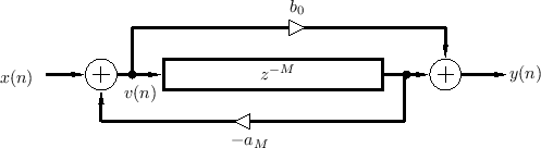
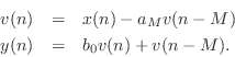
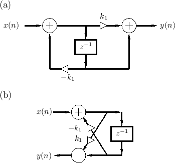
Figure 2.30 shows a combination feedforward/feedback comb filter structure which shares the same delay line.3.13 By inspection of Fig.2.30, the difference equation is
This can be recognized as a digital filter in direct form II
[449]. Thus, the system of Fig.2.30 can be interpreted as
the series combination of a feedback comb filter (Fig.2.24) taking
![]() to
to ![]() followed by a feedforward comb filter (Fig.2.23)
taking
followed by a feedforward comb filter (Fig.2.23)
taking ![]() to
to ![]() . By the commutativity of LTI systems, we can
interchange the order to get
. By the commutativity of LTI systems, we can
interchange the order to get
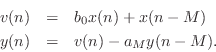
Substituting the right-hand side of the first equation above for
![]() in the second equation yields more simply
in the second equation yields more simply
This can be recognized as direct form I [449], which requires
The coefficient symbols ![]() and
and ![]() here have been chosen to
correspond to standard notation for the transfer function
here have been chosen to
correspond to standard notation for the transfer function

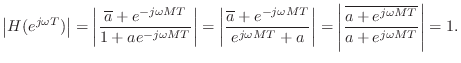
An allpass filter is obtained when
![]() , or, in the case
of real coefficients, when
, or, in the case
of real coefficients, when ![]() . To see this, let
. To see this, let
![]() . Then we have
. Then we have
Nested Allpass Filters
An interesting property of allpass filters is that they can be
nested [412,152,153].
That is, if ![]() and
and
![]() denote unity-gain allpass transfer functions, then both
denote unity-gain allpass transfer functions, then both
![]() and
and
![]() are allpass filters. A proof can be
based on the observation that, since
are allpass filters. A proof can be
based on the observation that, since
![]() ,
, ![]() can
be viewed as a conformal map
[326] which maps the unit circle in the
can
be viewed as a conformal map
[326] which maps the unit circle in the ![]() plane to itself;
therefore, the set of all such maps is closed under functional
composition. Nested allpass filters were proposed for use in artificial
reverberation by Schroeder [412, p. 222].
plane to itself;
therefore, the set of all such maps is closed under functional
composition. Nested allpass filters were proposed for use in artificial
reverberation by Schroeder [412, p. 222].
An important class of nested allpass filters is obtained by nesting first-order allpass filters of the form
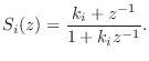
![$\displaystyle H_2(z) \isdef S_1\left([z^{-1}S_2(z)]^{-1}\right) \isdef \frac{k_1+z^{-1}S_2(z)}{1+k_1z^{-1}S_2(z)}.
$](http://www.dsprelated.com/josimages_new/pasp/img609.png)
The equivalence of nested allpass filters to lattice filters has computational significance since it is well known that the two-multiply lattice sections can be replaced by one-multiply lattice sections [297,314].
 |
![\includegraphics[width=4.45in]{eps/aptwo}](http://www.dsprelated.com/josimages_new/pasp/img612.png) |
In summary, nested first-order allpass filters are equivalent to lattice filters made of two-multiply lattice sections. In §C.8.4, a one-multiply section is derived which is not only less expensive to implement in hardware, but it additionally has a direct interpretation as a physical model.
More General Allpass Filters
We have so far seen two types of allpass filters:
- The series combination of feedback and feedforward comb-filters is allpass when their delay lines are the same length and their feedback and feedforward coefficents are the same. An example is shown in Fig.2.30.
- Any delay element in an allpass filter can be replaced by an allpass filter to obtain a new (typically higher order) allpass filter. The special case of nested first-order allpass filters yielded the lattice digital filter structure of Fig.2.32.
Definition:
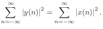
A linear, time-invariant filter ![]() is said to be
lossless if it preserves signal
energy for every input signal. That is, if the input signal is
is said to be
lossless if it preserves signal
energy for every input signal. That is, if the input signal is
![]() , and the output signal is
, and the output signal is
![]() , we must have
, we must have
Notice that only stable filters can be lossless since, otherwise,
![]() is generally infinite, even when
is generally infinite, even when
![]() is finite. We
further assume all filters are causal3.14 for
simplicity. It is straightforward to show the following:
is finite. We
further assume all filters are causal3.14 for
simplicity. It is straightforward to show the following:
It can be shown [449, Appendix C] that stable, linear,
time-invariant (LTI) filter transfer function ![]() is lossless if
and only if
is lossless if
and only if
Thus, ``lossless'' and ``unity-gain allpass'' are synonymous. For an
allpass filter with gain ![]() at each frequency, the energy gain of the
filter is
at each frequency, the energy gain of the
filter is ![]() for every input signal
for every input signal ![]() . Since we can describe
such a filter as an allpass times a constant gain, the term
``allpass'' will refer here to the case
. Since we can describe
such a filter as an allpass times a constant gain, the term
``allpass'' will refer here to the case ![]() .
.
Example Allpass Filters
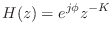
- The simplest allpass filter is a unit-modulus gain
where

 can be any phase value. In the real case
can only be 0 or
can be any phase value. In the real case
can only be 0 or  , in which case
 .
.
- A lossless FIR filter can consist only of a single nonzero tap:
for some fixed integer
 , where is again some constant phase,
constrained to be 0 or in the real-filter case. Since we are
considering only causal filters here,
, where is again some constant phase,
constrained to be 0 or in the real-filter case. Since we are
considering only causal filters here,  . As a special case of
this example, a unit delay
. As a special case of
this example, a unit delay
 is a simple FIR allpass filter.
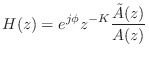
- The transfer function of every finite-order, causal,
lossless IIR digital filter (recursive allpass filter) can be written as
where,
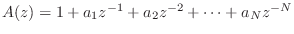 , and
, and
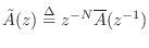 . The polynomial
 can be obtained by reversing the order of the coefficients in
 and conjugating them. (The factor
  serves to restore
negative powers of
serves to restore
negative powers of  and hence causality.)
Gerzon Nested MIMO Allpass
An interesting generalization of the single-input, single-output Schroeder allpass filter (defined in §2.8.1) was proposed by Gerzon [157] for use in artificial reverberation systems.
The starting point can be the first-order allpass of Fig.2.31a on
page ![]() , or the allpass made from two comb-filters depicted
in Fig.2.30 on
page
, or the allpass made from two comb-filters depicted
in Fig.2.30 on
page ![]() .3.15In either case,
.3.15In either case,
- all signal paths are converted from scalars to vectors of dimension
 ,
,
- the delay element (or delay line) is replaced by an arbitrary
 unitary matrix frequency response.3.16
Let
![]() denote the
denote the ![]() input vector with components
input vector with components
![]() , and let
, and let
![]() denote
the corresponding vector of z transforms. Denote the
denote
the corresponding vector of z transforms. Denote the ![]() output
vector by
output
vector by
![]() . The resulting vector difference equation becomes,
in the frequency domain (cf. Eq.
. The resulting vector difference equation becomes,
in the frequency domain (cf. Eq.![]() (2.15))
(2.15))
Note that to avoid implementing
![]() twice,
twice,
![]() should
be realized in vector direct-form II, viz.,
should
be realized in vector direct-form II, viz.,

where ![]() denotes the unit-delay operator (
denotes the unit-delay operator (
![]() ).
).
To avoid a delay-free loop, the paraunitary matrix must include at
least one pure delay in every row, i.e.,
![]() where
where
![]() is paraunitary and causal.
is paraunitary and causal.
In [157], Gerzon suggested using
![]() of the form
of the form
![$\displaystyle \mathbf{D}(z) = \left[ \begin{array}{ccccc} z^{-m_1} & 0 & 0 & \d...
...ts & \ddots& \vdots\\ 0 & 0 & 0 & \dots & z^{-m_N} \end{array} \right] \protect$](http://www.dsprelated.com/josimages_new/pasp/img652.png)
is a diagonal matrix of pure delays, with the lengths
Gerzon further suggested replacing the feedback and feedforward gains
![]() by digital filters
by digital filters ![]() having an amplitude response
bounded by 1. In principle, this allows the network to be arbitrarily
different at each frequency.
having an amplitude response
bounded by 1. In principle, this allows the network to be arbitrarily
different at each frequency.
Gerzon's vector Schroeder allpass is used in the IRCAM Spatialisateur [218].
Next Section:
Allpass Digital Waveguide Networks
Previous Section:
Feedback Delay Networks (FDN)


