


Passive Reflectance Synthesis--Method 1
The first method is based on constructing a passive reflectance
![]() having the desired poles, and then converting to an
admittance via the fundamental relation
having the desired poles, and then converting to an
admittance via the fundamental relation
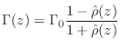
As we saw in §C.11.1, every passive impedance corresponds
to a passive reflectance which is a Schur function (stable and having gain
not exceeding ![]() around the unit circle). Since damping is light in a
guitar bridge impedance (otherwise the strings would not vibrate very long,
and sustain is a highly prized feature of real guitars), we can expect the
bridge reflectance to be close to an allpass transfer function
around the unit circle). Since damping is light in a
guitar bridge impedance (otherwise the strings would not vibrate very long,
and sustain is a highly prized feature of real guitars), we can expect the
bridge reflectance to be close to an allpass transfer function ![]() .
.
It is well known that every allpass transfer function can be expressed as
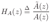
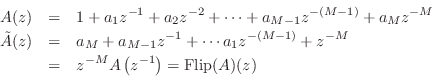
We will then construct a Schur function as
Recall that in every allpass filter with real coefficients, to every pole
at radius ![]() there corresponds a zero at radius
there corresponds a zero at radius ![]() .10.7
.10.7
Because the impedance is lightly damped, the poles and zeros of the
corresponding reflectance are close to the unit circle. This means that at
points along the unit circle between the poles, the poles and zeros tend to
cancel. It can be easily seen using the graphical method for computing the
phase of the frequency response that the pole-zero angles in the allpass
filter are very close to the resonance frequencies in the corresponding
passive impedance [429]. Furthermore, the distance of
the allpass poles to the unit circle controls the bandwidth of the
impedance peaks. Therefore, to a first approximation, we can treat the
allpass pole-angles as the same as those of the impedance pole angles, and
the pole radii in the allpass can be set to give the desired impedance peak
bandwidth. The zero-phase shaping filter ![]() gives the desired mode
height.
gives the desired mode
height.
From the measured peak frequencies ![]() and bandwidths
and bandwidths ![]() in the guitar
bridge admittance, we may approximate the pole locations
in the guitar
bridge admittance, we may approximate the pole locations
![]() as
as
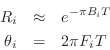
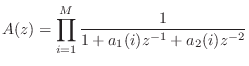
where ![]() is the sampling interval as usual. Next we construct the
allpass denominator as the product of elementary second-order sections:
is the sampling interval as usual. Next we construct the
allpass denominator as the product of elementary second-order sections:
Now that we've constructed a Schur function, a passive admittance can be computed using (9.2.1). While it is guaranteed to be positive real, the modal frequencies, bandwidths, and amplitudes are only indirectly controlled and therefore approximated. (Of course, this would provide a good initial guess for an iterative procedure which computes an optimal approximation directly.)
A simple example of a synthetic bridge constructed using this method
with ![]() and
and ![]() is shown in Fig.9.10.
is shown in Fig.9.10.
![\includegraphics[width=\twidth]{eps/lguitarsynth}](http://www.dsprelated.com/josimages_new/pasp/img2028.png)
Next Section:
Passive Reflectance Synthesis--Method 2
Previous Section:
Building a Synthetic Guitar Bridge Admittance


