


Racing to Sleep
Today we’re going to talk about low-power design.
Suppose I’m an electrical engineer working with wildlife biologists who are gathering field data on the Saskatchewan ringed-neck mountain goat. My team has designed a device called the BigBrotherBear 2000 (BBB2000) with a trip cable and a motor and a camera and a temperature sensor and a hot-wire anemometer and a real-time clock and an SD card and a battery and a LoRa transceiver. The idea is something like this:
- Every 15 minutes, the BBB2000 measures temperature and wind speed, and stores them to the SD card
- If the trip cable gets run over, the following sequence of events occurs:
- the camera takes some number of pictures in rapid succession and stores them to the SD card
- 5 minutes later, the motor rewinds the trip cable so it is ready to go again
- Every 24 hours, the BBB activates the LoRa transceiver and transmits its data to a base station a few kilometers away
There are anywhere between 5 and 20 BBB2000 devices per base station. The base stations then relay that data via satellite modem to the Internet, accessible at SaskatchewanRingedNeckMountainGoat.info by wildlife biologists throughout the world, so that everyone can see pictures of surprised mountain goats after they trip over a cable.
The biologists literally have a ton of 12V 5Ah batteries (625 of them at 1.6kg apiece) stacked up in a closet, thanks to a generous donor, so that’s the power source for the BBB2000.
Here’s the question: how often does the newest grad student have to head out into the backcountry schlepping batteries to the BBB2000s to switch them out with freshly-charged replacements?
Power Budgets
To answer this sort of question, we need to go through the exercise of a power budget.
There are a number of factors here, but basically it boils down to treating our system as having a quiescent low-power draw, and a number of events; for each event we need to know:
- how much energy it uses (or charge, as referenced to battery voltage)
- how frequently it occurs
That’s it!
So let’s go through our system and figure this stuff out. (Note to the pedantic reader: since this is a fictional situation, I’m just making a lot of these numbers up from reasonable estimates.)
-
Temperature and wind speed — 15 minute intervals; the temperature measurement is very low power (<100μA) and can be sampled in a few milliseconds, but the hot-wire anemometer draws up to 20mA and takes 2 seconds to stabilize before we can take a reading, so that’s 40mC.
-
Camera and motor — typical trip events occur anywhere from 2-10 times per day
- Camera — some measurements show that the camera uses about 0.32mAh = 1.15C from the battery per shot. The biologists like to get 5 pictures per trip event over 2 seconds.
- Motor — the trip cable typically loosens by about 1.2m from taut to tripped, and draws 100mA from the battery for about 20 seconds to rewind, so that’s 2C of charge.
-
LoRa transceiver — once per day. Using an RN2903, depending on the transmit power level needed, it takes anywhere from 50mA - 125mA at 3.3V to communicate with the base station at a 12500bps rate. There’s typically 10MB of data each day (mostly from the camera pictures); the BBB2000 team estimated 80% protocol efficiency, or 10000bps for data payloads after protocol overhead is subtracted. This takes 8000 seconds, or about 2 hour and 13 minutes, to transmit, and was a major source of contention with the wildlife biologists, which we’ll talk about in a bit. The BBB2000 uses a DC/DC converter from 12V to 3.3V with about 90% efficiency at 50-250mA output current, 80% at 10mA output current, and 70% efficiency at 1mA current. Lots of “it depends” answers around here, but if we calculate 100mA at 3.3V transmission × (3.3/12) / 0.9 = 30.6mA drawn from the 12V battery; 30.6mA × 8000s = 245C of charge.
If we figure out this stuff on a per-day basis, we get:
- temperature and wind speed — 40mC × 1440 minutes/day / 15 minutes (96 times per day) = 3.84C
- camera — max of 50/day * 1.15C = 57.5C
- motor — max of 10/day * 2C = 20C
- transceiver — 245C
Did we forget anything?
Oh right, we need some kind of microcontroller to run this thing, with power switches to turn things on and off so they don’t suck up battery power when they’re not running. Let’s just say your typical microcontroller needs 50mA from 3.3V while running at full speed and doing lots of calculations (about 15mA from the 12V battery), but it can be set in a low-power mode to draw 14mA from 3.3V (about 4mA from 12V) when operating at 10% of full speed, and some very small current \( I_{pd} \) when sleeping. Let’s say the SD card also needs about 50mA current from 3.3V (15mA from 12V) for 0.5second to write data, whether it’s 10 bytes or 1 megabyte. These aren’t necessarily great estimates, but we’ll come back and revise them if we need to.
- SD card: 15mA × 0.5s = 7.5mC; frequency = 96 times for the temperature/wind speed measurements, up to 50 times for pictures, for a total of 1.1C (0.72C for temp/wind speed, 0.38C for pictures)
- microcontroller:
- full-speed mode (15mA) for data transmission and camera use:
- 8000s = 120C for data transmission
- 50/day × 2s = 1.5C for camera use
- low-power mode (4mA) for motor and temperature/wind speed measurements (these don’t need lots of calculations from the CPU, we don’t need full-speed mode)
- 10/day × 20s = 0.8C for motor use
- 96/day × 2s = 0.77C for temperature/wind speed measurements
- full-speed mode (15mA) for data transmission and camera use:
Is the quiescent current \( I_{pd} \) important here? Well, it depends on how we get the power. A DC/DC converter might have awful efficiency at sub-1mA current, since it has its own quiescent current; maybe we switch off the DC/DC converter and use a low-quiescent-current linear regulator when the microcontroller is in its sleep mode. Or we could power our microcontroller off of a supercapacitor when it is in sleep mode — remember, the longest it would be in sleep mode is the 15 minutes (900s) between temperature/wind speed measurements. That’s 900μC / μA — it’s easy to make a 3.3V 1F capacitor bank to hold 3.3C. A 100μA current draw would use 90mC, which is small enough that if we use a 3.3C supercapacitor energy reservoir, there wouldn’t be much voltage droop, so a supercapacitor might be a good idea during sleep. And then we could take advantage of the DC/DC converter’s 90% efficiency to recharge it. Anyway if we have 100μA operating 24 hours a day, that’s 8.64C at 3.3V, converted from about 2.6C at 12V. This is much lower compared to the camera and transceiver that we don’t need to worry:
- trying to find a microcontroller with ultra-low current doesn’t make sense; we don’t care if it is 10μA or 100μA
- but we do care if its quiescent current is, say, 10mA.
Maybe there are a few other analog components but they take only a small fraction of the microcontroller’s current since they are turned off when not in use, and we can ignore them.
Anyway, the net total charge per day drawn from the 12V battery is:
- temperature and wind speed: 3.84C + 0.72C for SD card + 0.77C from microcontroller = 5.33C
- camera: 57.5C + 0.38C for SD card + 1.5C from microcontroller = 59.4C
- motor: 20C + 0.8C from microcontroller = 20.8C
- data transmission: 245C + 120C from microcontroller = 365C
Total: 450.5C / day = 125mAh (1000mAh = 1A × 3600s = 3600C)
So we can expect about 40 days operation (5000mAh / 125mAh/day) from our 12V battery before having to replace it with a freshly-charged battery.
And that’s a power budget. This one was somewhat handwavy; a real power budget for a device in production would have more careful accounting, but it’s the same idea. There are a few key principles here:
The Protruding Stake Is Hammered Down
(出る杭は打たれる Deru kui wa utareru — Japanese proverb)
To find ways of reducing power, go after the largest energy usages, not the smallest. In the BBB2000 example, the largest culprit is data transmission, using 365/450 = 81% of energy drawn from the battery. One way around this might be to download thumbnails of images rather than the pictures themselves, and then download the more interesting pictures later. (Or just replace the SD cards and bring them back when the battery is replaced, which doesn’t require any network traffic, kind of like El Paquete Semanal.)
For example, the thumbnail below of a jaguar is 43kB, whereas the larger picture I converted it from was 280kB.
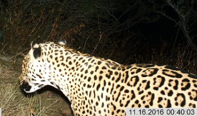
If we could cut down the data transmitted by 80%, then we could reduce the daily data transmission costs from 365C to 73C and the total cost from 450.5C/day to 158.5C/day = 44mAh/day, extending battery life from 40 days to 113 days between replacements. (Perhaps you can imagine the arguments between junior grad students who have to go off into the field during winter, because the batteries don’t last as long, and senior biologists who want the high-resolution images without having to be picky about what they can download. Maybe we should just try to find some solar panels for the BBB2000 and hope the sun keeps shining.)
On the other hand, cutting down quiescent microcontroller current from, say, 100μA to 10μA draw at 3.3V gets us from 2.6C/day to 0.26C/day, which is a drop in the bucket of the total 450.5C/day cost — which is why I said for this application that we shouldn’t bother trying to reduce quiescent current that’s only a small fraction of the total energy use.
If you’ve been reading my articles before, and this point sounds vaguely familiar, maybe you’re thinking about the one on Amdahl’s Law / Gustafson’s Law which covers the same principle.
It’s the Energy, Not the Power, Stupid!
The topic of low-power design should really be called low-energy design, because in the end it’s the energy that matters. I could have a laser that draws 1kW of power and fires for a total of 10μs a day, along with a 1μW continuous load. Which one uses less energy? 1kW × 10μs = 0.01J, whereas 1μW × 86400s = 0.086J — so the kilowatt pulsed laser uses only 1/8 as much as the microwatt continuous load.
As always, whether or not the quiescent power draw dominates depends on the circumstances, so do the math.
Racing to Sleep (What’s the Frequency, Kenneth?)
There’s a corollary to the previous point — suppose the bulk of the work I’m doing with my microcontroller is number-crunching. I have to run some algorithm (maybe it’s taking wildlife photographs and converting them to smaller thumbnails) and then go to sleep, until I wake up and do it all over again. What CPU clock frequency should I use? Should I run in a low-power mode, or full speed?
If the CPU work is computation-bound — meaning I’m waiting for a certain number of instructions to run, rather than waiting for some external task to complete like an Ethernet packet to arrive or a bunch of ADC samples to complete — then the best answer is almost always to run in the full-power mode. We “race to sleep”; this sounds somewhat counterintuitive, but often the relationship between clock speed and power draw depends on two things:
- static power consumption — there are things in the microcontroller that draw the same amount of power, independent of clock frequency, like voltage regulators or analog circuitry
- dynamic power consumption — modern CMOS logic uses most of its power (and energy!) charging and discharging the total parasitic capacitance of the gates of transistors. It’s all about \( CV^2f \); doubling the clock frequency doubles the power requirement.
If we look at one of the characterization graphs (Fig 32-6) of the dsPIC33EP256MC506, we can see this behavior:

The power draw is mostly linear with clock frequency, but intercepts the y-axis above zero: even with 0 MIPS, we’ll still draw some static power. I’m going to eyeball the data in Fig 32-6 and say that it fits a curve for worstcase \( I_{dd} \approx \) 10mA + 0.75mA/MIPS.
When we look at the energy usage as a function of the number of cycles, and all we change is the CPU clock frequency, then the dynamic energy consumption doesn’t change. 1000 cycles at, say, 0.75mA for 1MIPS operation takes us 1ms and uses 0.75μC of charge; 1000 cycles at 7.5mA for 10MIPS operation takes us 0.1ms and also uses 0.75μC of charge. What does change is the charge we need to support static power consumption during these intervals. The faster clock frequency lets us get the same job done faster, so we need less energy for static power consumption. So race to sleep!
It gets more complicated if the CPU core voltage is allowed/required to change (again, it’s all about \( CV^2f \)); in your case, figure out your options and do the math.
External Circuitry: Waiting for Godot
Not every task in low-power design is computation-bound. If you’re working with external hardware like motors or an RF radio, or even internal peripherals like an ADC or a UART, the CPU might be waiting around a lot for those circuits to do their work, and in that case, running in a lower-power mode can use less energy for the same required tasks. In the extreme, where the CPU needs to wait for hundreds of milliseconds or even seconds for something else to do its thing, the optimal strategy may be worth going to sleep and having some external circuit wake up the processor when it is done.
The tough situations are when there are a LOT of very short time delays; for example, if we have to wait 100 cycles for some ADC cycle to finish, and it happens 1000 times a second, amid a bunch of other computations, then there’s no way we can take advantage of a low-power mode. The overhead of trying to get to sleep or switch in and out of power modes is too high. It’s kind of like when a three-year-old child keeps pestering you every few minutes while you’re trying to get something done; sometimes you wish you could just clonk them over the head and make them take a nap for a few hours. The best we can hope for is to try to schedule some computations in parallel with the short time delay, rather than sit there and waiting for 100 cycles. This gets messy from a good software design standpoint (your algorithms are implemented in a way that is more closely coupled to the behavior of the thing you’re waiting for) but sometimes it’s the only way to save energy.
Powering Up Is Hard to Do
One thing that’s easy to overlook is the amount of energy for a microcontroller to come out of sleep. It’s not an instant transition from sleep to running at full speed. This, of course, depends on a number of things, but the two dominant ones, in my experience, are the following:
- time for the clock to get up and running again
- time for the program to get over any “disorientation” from sleep and continue what it was doing.
Consider the dsPIC33EP256MC506 again. (It’s definitely not one of the lowest-power 16-bit microcontrollers, but you’re stuck with it as an example because that’s the one I’m most familiar with.) It has a spec (OS52) of 3.1ms max for the PLL oscillator to lock properly. This is going to dictate the time, and the energy, it takes each time we want to come out of a sleep mode and into full-power operation. If I just need to check a few things and go back to sleep, then maybe I don’t want to run at full speed after all; this part has a fast 7.37MHz RC oscillator that takes a maximum of 54μs (SY37) to start up.
I estimated earlier from the graph in Fig 32-6 that worstcase \( I_{dd} \approx \) 10mA + 0.75mA/MIPS, so let’s say our alternatives are:
- full speed (70 MIPS, fosc = 140MHz): draws 60mA, takes 3.1ms ≈ 186μC to start up
- fast RC at low speed (3.685MIPS, fsoc = 7.37MIPS): draws 13mA, takes 54μs ≈ 0.7μC to start up
Which of these we might want to choose depends on the number of instructions we need to run. At the extremes, if we execute no instructions before going back to sleep, the fast RC oscillator makes more sense (0.7μC vs. 186μC), whereas if we have thousands of instructions, the full-speed oscillator is more power-efficient, with 19 times the CPU speed at about 4.5 times the current.
%matplotlib inline
import numpy as np
import matplotlib.pyplot as plt

n_instructions = np.arange(0,160000,100)
q_fullspeed = 60e-3 * (3.1e-3 + n_instructions / 70.0e6)
q_fastrc = 13e-3 * (54e-6 + n_instructions / 3.685e6)

fig = plt.figure()
ax = fig.add_subplot(1,1,1)
ax.plot(n_instructions, q_fullspeed*1e6, color='red', label='fullspeed')
ax.plot(n_instructions, q_fastrc*1e6, color='blue', label='fast RC')
ax.legend(loc='best', fontsize=10)
ax.set_ylabel('charge used, uC')
ax.set_xlabel('# of instruction cycles')
ax.grid(True)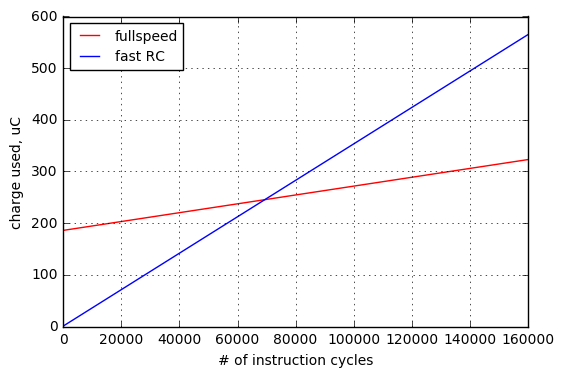
This analysis is somewhat surprising: the breakeven point isn’t until about 70,000 cycles! So if you’re using this part and you have, say, 40,000 instruction cycles to perform before going back to sleep for 10 minutes, you’ll use less energy if you just stay in FRC mode.
The other aspect of the powering up “cost” is that some parts offer sleep modes that cause the firmware program to lose context. The PIC24FJ256GA412 family has an ultra-low 80nA typical (800nA max) current draw when in “deep sleep” at Vdd = 2V, but the price you pay for this low-power draw is that the RAM is left unpowered and the device wakes up from sleep in a reset state rather than resuming from the program address where it entered deep sleep. (You get two 16-bit context registers DSGPR0 and DSGPR1 which do retain their value during deep sleep, so critical flags or state machine states could be saved there.) There are a number of different low-power modes in this device:

The question is, when should we use deep sleep vs. “ordinary” sleep? (DC70 = 80nA typ for deep sleep at 2V, 25°C; DC61 = 630nA typ for low-voltage sleep at 2V, 25° C) If we’re using the 8MHz (4MIPS) internal FRC oscillator on these parts, typical operating current DC23 = 1mA.
Suppose our firmware takes 1000 cycles (250μsec) to reconstruct the state it was in, after coming out of deep sleep, whereas with the other low-power modes we can restart right away. Those 1000 cycles at 4MIPS operation are worth 1mA × 250μsec = 0.25μC of charge, which we get back after 0.25μC / (630nA - 80nA) = 450ms of time in sleep — any longer and deep sleep uses less energy.
If our firmware takes 100 cycles to reconstruct its program state, we break even with deep sleep being attractive after 45ms of sleep.
If our firmware takes 10,000 cycles to reconstruct its program state, we break even with deep sleep being attractive after 4.5s of sleep.
At any rate, you can’t just look at the quiescent power; each of the sleep modes incurs different costs to come out of sleep and re-enter normal operation.
Measure, don’t assume!
The datasheet will have numbers that give you an idea of how much power a device draws, or how long it takes to come out of sleep.
If you have a really critical system design decision, don’t just use the datasheet — check with real measurements! They may be subject to variations in operating conditions (temperature, part-to-part variation, etc.) but they will give you actual measurements rather than on-paper calculations.
It can be really tricky to make some of these measurements, especially when you have a wide dynamic range of current consumption — for example, alternating 10μA and 10mA for Idd — and my best advice is to use a small series resistor in the Vdd line of your circuit board, along with an RC filter and a high-input-impedance low-offset-voltage amplifier to measure that voltage drop in the sense resistor. Don’t expect high gain and high dynamic range and high bandwidth and high accuracy all in the same op-amp circuit. What you care about is charge drawn over a certain time window, so high bandwidth isn’t usually needed.
References
I touched on only a few areas of low-power design. For more information, see these application notes:
- AN606 Low Power Design Using PICmicro™ Microcontrollers — from 1997, but the overall principles are still valid today
- PIC® Microcontroller Low Power Tips ‘n Tricks
- AN1267 eXtreme Low-Power (XLP) PIC® Microcontrollers: An Introduction to Microchip’s Low-Power Devices
- AN1416 Low Power Design Guide (2011)
Some academic papers on the idea of “racing to sleep” are:
- Racing and Pacing to Idle: Theoretical and Empirical Analysis of Energy Optimization Heuristics (2015)
- Power Optimization - a Reality Check (2009)
Wrapup
We talked about a number of areas of low-power design today:
- Don’t guess; make a power/energy budget by measuring quiescent current and the charge drawn over each event that takes the system out of a quiescent state — remember, charge = current × time
- The system aspects that cause the highest energy usage are very dependent on circumstances; don’t guess, make a power/energy budget
- Power conversion efficiency matters when the power source is at one voltage, and the consuming electronics is at another
- Budgeting accuracy and power savings are most critical for the parts of the system that use the most energy
- When events are short and infrequent, energy matters, not power
- Racing to sleep is the principle that for the same number of instruction cycles (= tasks that are computation-bound), dynamic power consumption (mA/MIPS) leads to the same amount of charge consumed, whereas static power consumption leads to less charge consumed if we run at a higher clock frequency and finish faster
- Running at a low-power mode is often important when there are tasks that are not computation-bound, but depend on waiting for some other device that uses power
- Going to a low-power mode has an energy cost to wake up and wait for the oscillator to stabilize, and to recover system state (in cases w/o retention of RAM or the program counter) — do your homework, because when you’re looking for the lowest overall energy consumption:
- sometimes it doesn’t always make sense to go into the lowest power mode, because it costs more to wake up
- sometimes it doesn’t always make sense to wake up and race to sleep at the fastest clock frequency, because it costs more for that clock frequency to become operational
- Measure your system’s current draw! It will sanity-check your calculations.
- It’s worth repeating: Don’t guess — make a power/energy budget!
Got any more low-power hints? Let me know!
Best of luck saving energy in your designs, and have a great new year!
© 2019 Jason M. Sachs, all rights reserved.


- Comments
- Write a Comment Select to add a comment
To post reply to a comment, click on the 'reply' button attached to each comment. To post a new comment (not a reply to a comment) check out the 'Write a Comment' tab at the top of the comments.
Please login (on the right) if you already have an account on this platform.
Otherwise, please use this form to register (free) an join one of the largest online community for Electrical/Embedded/DSP/FPGA/ML engineers:


