


Two Capacitors Are Better Than One
I was looking for a good reference for some ADC-driving circuits, and ran across this diagram in Walt Jung’s Op-Amp Applications Handbook:
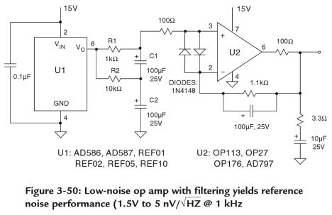
And I smiled to myself, because I immediately remembered a circuit I hadn’t used for years. Years! But it’s something you should file away in your bag of tricks.
Take a look at the RC-RC circuit formed by R1, R2, C1, and C2. It’s basically a stacked RC low-pass filter. The question is, why are there two capacitors?
I discovered this type of approach myself a few months after I graduated from college and was working on some battery testing circuits. We needed a really slow RC filter, with a 10 second time constant. Really simple, right?
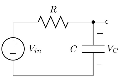
I picked R = 10MΩ and C = 1μF, and followed the RC circuit with a good CMOS-input opamp follower with guaranteed maximum input bias current in the picoampere range.
There’s a problem here, though.
Let’s look at the specification for the Murata GRM219R71E105KA88, a 1μF 25V X7R 0805 capacitor. If you look at page two of the spec, under Insulation Resistance it says:
C ≤ 0.047μF: More than 10000MΩ
C > 0.047μF: More than 500 Ω⋅F
For small capacitors, this means the insulation resistance is at least 10GΩ, but for large capacitors, they state it in terms of a resistance - capacitance product, equivalent to a time constant, of 500 seconds. For my 1μF capacitor, it would be 500MΩ minimum insulation resistance.
That’s right, there’s parasitic parallel resistance:

And what it means is we have a voltage divider. Worst case, we’d have R = 10MΩ and Rp = 500MΩ, for a net DC gain of 500 / 510 ≈ 0.98. With a 12V battery, that would show up as VC = 11.76. Yuck! That’s almost a quarter-volt of error.
That spec is worst-case; I don’t remember what I ran into when I was working on the battery tester project, it might have been maybe 10 or 20 millivolts sag due to leakage through the capacitor’s insulation resistance. A 5GΩ insulation resistance would have had a gain of 0.998, with a sag of 24mV on a 12V battery. (And with high-impedance nodes, you’ve also got to be careful about keeping your circuit board clean so there’s not a leakage path on the board through moisture or leftover solder flux.)
And there’s really nothing you can do about it if you use this circuit topology, unless you’re willing to pay for ultra-low-leakage capacitors. You might think, hey, I can just raise the resistance and lower the capacitance by a factor of 5 or 10, but then the parasitic resistance will scale also, and in the end things won’t really change.
But one solution to this is to use a second RC filter:
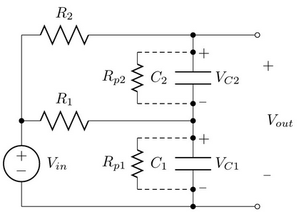
What happens now, is that most of the DC voltage appears across the lower capacitor. There’s still leakage. The remaining DC voltage, which is very small, appears across the upper capacitor.
For example, R1 = R2 = R = 10MΩ and Rp1 = Rp2 = Rp = 500MΩ. Then the DC voltage gain from Vin to VC1 is still about 0.98. The DC voltage gain from Vin − VC1 to VC2 is also about 0.98, so we have
$$ V_{out} = 0.98V_{in} + 0.98(V_{in} - 0.98V_{in}) \approx 0.9996 V_{in}$$
Now our output DC voltage for a 12V input is 11.995V, worst-case. (Typical insulation resistance will be higher so our gain is most likely going to be much closer to 1.)
As far as the AC characteristics, we can basically neglect Rp, and if I’ve done my algebra right, the transfer function from Vin to Vout is
$$ \frac{V_{out}}{V_{in}} = \frac{3RCs + 1}{s^2 + 3RCs + 1} = \frac{3RCs + 1}{(\tau_{p1}s + 1)(\tau_{p2}s + 1)}$$
where \( \tau_{p1} = \frac{3-\sqrt{5}}{2}RC \approx 0.38197RC \) and \( \tau_{p2} = \frac{3+\sqrt{5}}{2}RC \approx 2.618RC \).
What this means is that the highest frequency pole has a time constant that is only 0.38197 as much as our single-pole RC filter. The other pole and zero come into play at frequency about 7 times higher, and they’re close enough together that they don’t do much.
So if we want the same effective time constant of 10 seconds, we need capacitor values that are 2.6x higher.
If we choose C = 2.2μF and R = 12MΩ then that should suffice. In this case, the minimum insulation resistance should be 227MΩ and our factor of 0.98 turns into 227/(12+227) = 0.95, and the net DC gain is
$$ V_{out} = 0.95V_{in} + 0.95(V_{in} - 0.95V_{in}) \approx 0.9975 V_{in}$$
For a 12V battery this would mean we’re sensing 11.97V at the output. Sigh. A 30mV sag. We could stack a third stage, which would help the DC gain but make the frequency response worse, driving us to higher capacitor values to get an equivalent time constant. I’d probably stop at two stages and just live with the 0.9975V worst-case DC gain, which is at least much better than the 0.98 worst-case DC gain of the one-stage RC filter with leakage. And anyway, that’s worst-case; the insulation resistance of capacitors is usually higher.
But you get the idea. Two capacitors are better than one, when it comes to stopping leakage current.
The same approach works for high-pass filters. Just switch the R’s and C’s around:
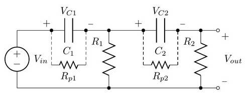
This time the capacitors are supposed to get rid of DC voltage. Most of it is gone when we look across resistor R1, and we add a second stage to get rid of most of the rest.
The other point to make is that it’s really hard to use analog circuitry for very long time constants (more than a few seconds). The circuits become very prone to parasitic leakage. Much better to do this kind of long time-scale low-pass filtering with digital signal processing, if you have a microcontroller around anyway. Then all you have to do in analog is enough filtering for anti-aliasing, and it’s a tradeoff between how fast you want to sample and run your computations in the digital domain, and how large the components are in the analog domain.
Summary
Capacitors have leakage current through their insulation. It’s usually specified in terms of a minimum time constant (Ω⋅F). This forms a DC voltage divider, forming an error voltage on a low-pass or high-pass filter.
You can decrease this error voltage by using a second RC stage. It essentially squares the relative error (0.02 → 0.0004). The only downside is that the RC time constant is decreased, and you need to adjust your RC values to compensate. But even after the compensation, the relative error is decreased by a second RC stage.
In any case, keep this idea in your bag of tricks.
© 2015 Jason M. Sachs, all rights reserved.


- Comments
- Write a Comment Select to add a comment
I like your articles. Though many of them go over my head. I have a question related to this article if I may.
How does temperature affect the performance of a capacitor? Does a capacitor work better/closer to its specification when it gets warm/hot? Does the life of a capacitor reduce if it's constantly running warm/hot?

If I remember correctly, capacitors have a higher leakage at higher temperature. Not sure about the capacitance; from looking at the definitions of the standard temperature designations (NP0, X7R, Y5V, etc) https://en.wikipedia.org/wiki/Ceramic_capacitor#Temperature_dependence_of_capacitance it looks like capacitance can either go up or down.
Lifetime definitely is reduced at elevated temperatures; Arrhenius's Law comes into play and the lifetime drops by about a factor of two for every 10 degree C rise.
To post reply to a comment, click on the 'reply' button attached to each comment. To post a new comment (not a reply to a comment) check out the 'Write a Comment' tab at the top of the comments.
Please login (on the right) if you already have an account on this platform.
Otherwise, please use this form to register (free) an join one of the largest online community for Electrical/Embedded/DSP/FPGA/ML engineers:


