


ADC can't perceive MLS (maximum length sequence)
I am developing a device for measuring impulse responses. I use MLS method (article for example: http://www.bg.ic.ac.uk/research/g.stan/ArticleJAES...), therefore I use DAC to generate the binary sequence and ADC to get responses for further calculations. Both ADC and DAC seems to work properly but I am not sure are they able to work with MLS.
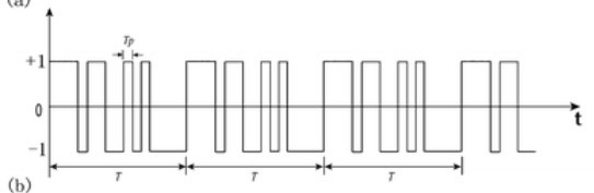
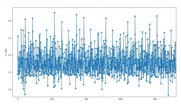
MLS is just a periodic pseudorandom binary sequence and it have to look like on the first attached picture. Also each value of MLS must be set on each sampling step. However, when I generate MLS with DAC and try to read it with ADC (DAC and ADC are linked directly) I get some strange chaotic set of values like on the second attached picture. So, if I can't get the sequence, any usage of the measurement method is impossible.
ADC and DAC sampling rates equal 48000 Hz. Possibly sampling rate should be higher but I have read articles about the MLS method and authors used even lower sampling rates.
My questions are:
Why cannot ADC perceive generated MLS?
What can I do to improve performance of the method?

Definitely start with a lower sequence rate, and lower them until you can see the sequence cleanly.
Also consider doubling the 'sample/bit rate' in the sense that you need to see the synchronous phasing effects. You can either ADC sample at the middle of the DAC settling, or make every PRBS bit hold for two sample times so that the changing edge at the DAC is sampled, and then the second sample is of the stable bit value.
The ideal is probably to sample the ADC just before the DAC value is changed, so as to give the cleanest signals (this can be tricky to set up).
Once you have the DAC/ADC timing clear in your mind, try a very simple Resistor-Capacitor circuit arranged as High and Low pass to see if the method works for you for a simple circuit(s), and go from there.
Dear philipoakley,
do you have some idea of the chip rate? you want to initially run your sampler at 4-samples per chip... not much faster or slower because the number of samples per chip will drift and make the correlation sequence jitter. The square wave version of your spreading sequence is not really band limited. With 4-samples per chip you are only seeing the mainlobe and first adjacent sidelobes of the power spectra. if you are lucky 3 of the samples will fit on each chip level with the 4-th on the midpoint of the transitions. anything less than 4 samples per chip will offer you poor chance of acquiring true peak value of correlator due to timing quantization....might want to start with 8 samples per chip and learn sensitivity to reduced number.
fred h

Hi forthan,
the first step is to make sure that what you are transmitting is actually a PN sequence. This sample Matlab code shows that this is indeed, a PN sequence. So do something similar with your sequence.
hold on;
h1=commsrc.pn('GenPoly',[5 3  0],'InitialStates', [ 0  0 0 0 1]);
set(h1, 'NumBitsOut', 3*2^5-1);
scrbits=2*generate(h1)'-1;
plot(xcorr(scrbits,scrbits(1:31)))
xlabel('lags');
ylabel('autocorrelation')
title('2^5-1 PN Sequence Autocorrelation')
to answer your inquiry about why you read where people would use lower sampling rate, be rest assured that there will be at least 2x oversampling at the receiver of the transmitted chip rate when correlating a PN sequence...what may be happening is that they are using oversampling for pulse shaping at the transmitter. This is often the case in twisted-pair Ethernet, and training sequences (like in single-pair Automotive Ethernet) are 2x oversampled. It's less oversampling than what professor harris mentioned because these channels are very lowpass.
finally, after you sort out your undersampling, your ADC picture has a lot of DC offset. It goes back to how are you transmitting the signal and what is the channel? For example, is it on-off keyed like non-coherent light source like an LED? There are sequences which are better than PN sequences for determining impulse response for these types of channels.
Thank you all very much, I solved problem. The sampling rates of ADC and DAC were too much different due to my wrong settings.


