


Hi Members,
I am familiar with polyphase filters and implementation to an extent, i am however trying to understand how to add parallelism in order to reduced clock speed and also reduce the amount of delay line required.
I am having trouble understanding the data mux logic for cases like P/Q=6/5(as an example), so for every 5 input samples , 6 outputs are generated, ie.. there are 6 filters but i want to introduced parallelism and calculate 2 filters simulataneously so that i can reduce clock speed , for example if the input clock is 500 and output clock is 600, i can lower the computation speed to 300 if i calculate 2 filter outputs at the same time. For this specific example, i think this may be better for power (at the cost of extra multipliers) because i can reduced the computation from clock speed 500 per filter to 300 per filter when done in parallel.Assuming there is a way to transfer data from 500 to 600 domain and the data @ 600 is as shown below
0 1 2 3 4 5 6 7 8 9 10, after deserializing to 300 data looks like 0 2 4 6 8 10(even samples),1 3 5 7 9 11(odd), my understanding is that in the cycle filter f(0),f(5) are calculated, in 2nd cycle, f(4),f(3) and in 3rd cycle f(2),f(1) are computed, but since i have to take only 5 inputs and would like to do a signle delay line and opposed to 2 delay lines ( save some resources) , i am always missing 1 data point when i try to line the data because to compute 2 outputs in parallel, i have to apply even and odd samples at the same time to the delay line, in othere words i have to shift the delay line by 2 samples but this would be a problem as i would miss one input sample from the computation but if i shift by 1 once and shift by 2 twice that would work but getting a predictable consistent set of delays elements for filter computation is becoming a problem, Any thoughts or ideas are very much appreciated . [Sorry for the long post :) ]
Attached is a picture to show you what i am thinking but i am missing something obviosuly. I assume the concept itself is correct but
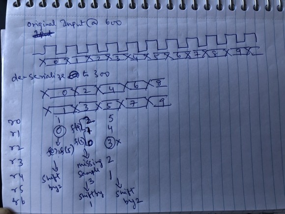
something in the way the data is getting interpreted .
Thanks in adavnce
CD
hello cdprasad,
I'm assuming you are building an analysis channelizer and you have designed the prototype with sufficiently narrow transition that it will not alias into passband at the 6/5 output sample rate...
you can run all filters in parallel if you want. Typically the lowest filter can start even before the first new sample arrives,,, and as each successive input sample arrives, the next filter is engaged to process that path... you don't have to wait till all 5 new inputs arrive...as each input arrives you can start the row to which the commutater delivered its output sample.
Is your platform a mircroprocessor or an fpga (or a matlab simulation)?
best regards
fred h
Hello Fred
Thanks for the response, i am trying to implement in an FPGA which already has a lot of logic as its an eval purchased.
I agree that i dont have to wait for all 5 samples to get shifted into the Delay line. So, the normal way would be run the polyphase sub-filters @ full output rate. My understanding is as follows
sample 0 sifted in-- filter(0) and filters(5) outputs are calculated
sample1 - shifted in ---filter(4) output is calculated
sample2 - shifted in ---filter(3) output is calculated
sample3 - shifted in ---filter(2) output is calculated
sample4 - shifted in ---filter(1) output is calculatedor 5 sample
so, for 5 input samples shifted , we have 6 output samples. So far so good
but i want to reduce the clock frequency so that i can get some timing margin in the FPGA, so i decded to run the filters @ 300 at the cost of the extra set of multipliers. i ended up forming the logic as shown below, now to run 2 filters in parallel @ 300, i deserialized the data into even/ odd samples, so that i can present 2 samples per clock to both filters but share a common delay line, this is where i think i am making some mistake, if i use 2 delay lines with the same data being present in both the delay line, its staright forward, but combining 2 delay lines into one needs some data distribution adjustment.
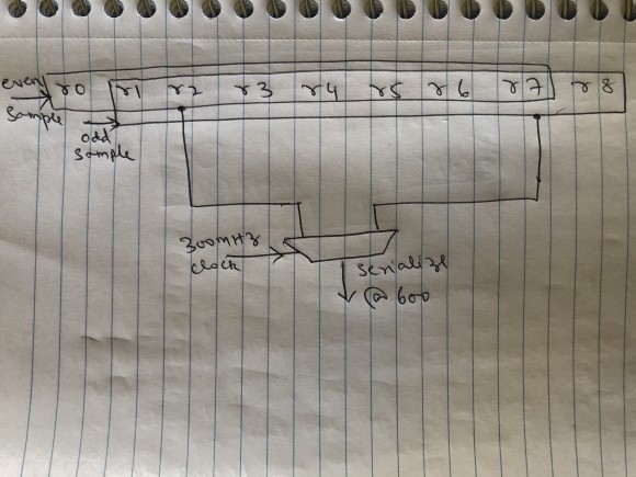
so , in the 1st,4th,7th cycleand so forth , we have to shift only one sample
in the 2nd,3rd,5th,6th,8th,9th cycle .... we shifht 2 samples in. but the fact that i shifht only one sample in 1st,4th,7th clock will cause one sample to slip as i am continuosly getting 2samples/clock and i am not sure how to avoid that slippage(hope i'm thinking thru this correctly). This is where i'm stuck.
Thnx
CD

If you were upsampling by 2 then two parallel polyphases will fit nicely one per path. But since you are upsampling by 6/5 then you need to break your prototype filter into two paths as below. It means more resource, more power but half Fmax within filtering module.
he = h(1:2:end); %even coeffs
ho = h(2:2:end); %odd coeffs
f1 = filter(ho,1,xe); %filter even input
f2 = filter(he,1,xo); %filter odd input
f3 = filter(he,1,xe); %filter even input
f4 = filter(ho,1,xo); %filter odd input
ye = [0 f1] + [0 f2]; %even output
yo = [f3 0] + [0 f4]; %odd output
y(1:2:end) = ye;
y(2:2:end) = yo;
How did I get that. Modelling tells, compare with (h) on its own and see after removing floating point effect.


