


Removing Attenuator (S -Parameter) influence on the received Baseband signal in Radar Transmitter - Radar signal processing
Radar Transmitter Measurement Setup:
Waveform Generatorr + IQ Transmitter + Attenuator + Real Downconversion mixer + Oscilloscope + Post Processing (Hilbert Transform)
With the above arrangement for the Radar IQ TX characterization, I need to remove the the influence of Attenuator and Real Downconversion mixer on the received real Baseband signal at the oscilloscope. At first, attenuator is characterized and corresponding S Parameter file is obtained. Similarly using RS ZVA67 VNA, the real downconversion mixer: RF to IF conversion loss (b2/a1) measurement is done.
My Understanding:
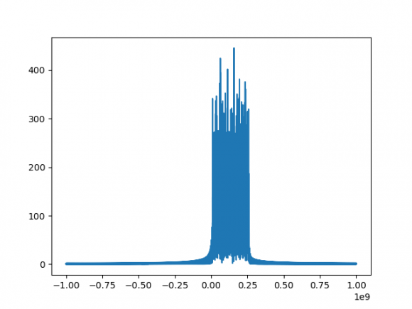
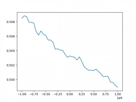
S Parameter of the attenuator shows large variation over the frequency range (It is converted to linear scale.) Since, the S Parameter refers to frequency domain, the received time domain baseband signal (Bandwidth = 250 MHz) at Oscilloscope is converted to frequency domain using 'FFT'. Since, both are in linear scale, subtraction of 2 signals (i.e FFT of the Baseband signal and S21 of attenuator) should be done to obtain original signal with no attenuation.
Note: I have 601 sample points in S Parameter file and 20480 sample points in Baseband signal both ranging from -1 GHz to 1 GHz (which is the bandwidth of interest)
Questions: Could you please correct my following understanding:
- Am I proceeding in correct direction: to subtract the two frequency domain signals to obtain the original signal
2. Should I have to scale any one of the signal comparable to other and also does phase of the two signals comes into picture?
3. The BW of interest is -1 GHz to 1 GHz. Therefore only 40 points (340 to 381) out of 601 in attenuator is considered. However, I have 20480 sample points of the Baseband signal which is also ranging from -1 GHz to 1 GHz. Since, 2 arrays of different shape (20480, 40), subtraction is not possible. Could you please let me know how can I proceed in this case?
4. I would be glad to know if there is any suggestion for change in
measurement setup for the above scenario (Note: The BB signal is
measured using Oscilloscope because later I need time domain signals for
IQ TX modelling)
Fig1. FFT of BB signal Fig2. S21 of Attenuator Fig 3. Superimposed BB and S21 signal


It's the right idea, but life isn't that simple. S parameters are complex numbers, so you have amplitude and phase. What you measure is the sum over all the reflections in the system. De-embedding uses a matrix inversion of all the S parameters to take those bounces into account. If you have a way to measure both amplitude and phase at each frequency of interest at the oscilloscope you can multiply that by the inverse of the mixer S parameters, then multiply that by the inverse of the attenuator S parameters and the result will be the S parameter matrix of the IQ transmitter. Pull an IFFT on that to get the time domain view.
A VNA instead of an o'scope will also accomplish this.
You can get a rough estimate ignoring phase and reflections if you look at power at each frequency - what went in vs what comes out. Especially if you measure at each stage with the 'scope. But that does not give you the whole picture.

For non-RF people: VNA = Vector Network Analyzer. This is a piece of lab equipment that is used to measure the complex S-parameters over some frequency range of a device or system, where:
S21 = forward frequency response
S12 = reverse frequency response
S11 = input reflection coefficient
S22 = output reflection coefficient
Thank you @drmike for your reply.
Digital IF concept is used. The plan is to obtain the quadrature signal from real baseband signal using Hilbert Transform in the post-processing and then use it for IQ Tx modelling.
1) The S Parameter of Attenuator is measured using VNA from 60-90 GHz, since I had to deembed it from the received baseband signal (10 to 250 MHz), I considered f_LO (Real Mixer) = 78 GHZ and subtracted it from each frequency points of S Parameter file to obtain -1GHz to 1 GHz range (i.e, x-axis of attenautor S Par is adapted to BB signal, however y axis values remains the same). Could you please correct me, if this is wrong approach.
2) For the Matrix inverse, should I consider inverse of only S21 (both mag and phase) matrix multiplied with baseband signal row matrix to obtain the original signal in this scenario. Is my understanding correct?
3) Received baseband signal is a row matrix with 20428 samples and S21 is a reshaped column matrix with 40 samples both having same frequency range -1 GHz to 1 GHz. Now, inorder to take inverse, how can I deal with remaining points. Could you please give your suggestion?
4) At oscilloscope, I will have real baseband signal and after Hilbert transform - the Inphase and Quadrature signal (complex) is obtained (=> mag and phase) and then I shall take the inverse of S Parameter (complex) of Mixer and Attenuator to obtain the original signal from IQ transmitter.
Thanks a lot for your time.
I don't think you can just shift the frequency and subtract. In the attenuator your signal is in the 78 GHz range. After the mixer your signal is in the 1 GHz range. So there are 78 cycles of noise that the attenuator can add to each cycle of your signal. The S parameters give you voltage and phase as a function of frequency which is useful if the entire system passes the same frequency. The whole point of a mixer is that it is nonlinear. There has to be some transfer across all frequencies to all other frequencies, and since I've never seen any text book discussion of it I assume that's really complicated.
Since you have a signal generator, you can just measure your system directly. Forget about S parameters. For a fixed LO, sweep the input signal across the range of interest (77 to 79 GHz?) as pure sine waves. What do get at the scope? This is a null base band. If you get a perfect zero voltage at all frequencies, your system is perfect! You should also do that at different input power levels because the mixer is nonlinear the noise level will be different at each level of power.
This measured data can be directly subtracted from your carrier+signal. It's not perfect because the mixer is nonlinear but it's a hell of a lot better than using S parameters of individual components.
Check out the recent book "S-Paramters for Signal Integrity" by Pupalaikis to see just how complicated even simple systems can get.
Thank you very much @drmike for your detailed reply.
1) Down-Conversion Mixer:
Since the ultimate goal is IQ Tx modelling and DPD, accurate measurement of additional components (Attenuator and DownConversion mixer) is required.
As you rightly pointed out, since frequency translation occurs in Mixer, the term 'S parameter' is not correct. To have accurate results, today complex mixer measurements were performed using ZVA 67 VNA (Power, Source, IF Calibration) (https://scdn.rohde-schwarz.com/ur/pws/dl_downloads...). Conversion Loss = a2/b1 = RF Power/IF Power is measured which is equivalent to S21. I am intending to use this S21 (Conversion loss) of Mixer for de-embedding from the Baseband signal. Could you please let me know if you see any mistake in this approach?
2) Attenuator:
I initially thought, 'since LO is fixed and I know BB bandwidth (0 GHz to 1 GHz), corresponding RF signal (Ex: 77 to 78 GHz) that is representing downconverted BB signal (20480 sample points) can be found' and 'then the sample points (40 to 85) corresponding to 77 to 78 GHz of S Parameter (both amp and phase info) of Attenuator and interpolate it such that it has more points (20480)' is implemented. Finally, as you mentioned earlier inverse of this S Parameter matrix is multiplied with BB signal and de-embedding is achieved. However, I understood your point about additional noise cycles. Does it have a huge influence on the accuracy even after the de-embedding procedure described previously? Do you have any suggestions for the removal of attenuator influence apart from using the S Parameter of individual components?
Sure, if I get a chance, I will have a look into the book mentioned by you.
Thanks a lot for your time.
Without a deep dive into the math I can't see anything wrong with your process. Should get you close.
As for "huge influence" it depends on how much signal to noise you want to recover. At the 10% level you can tell if this works. Measuring multiple power levels at multiple frequencies with fine gradations can get you a lot closer. Then you'd know if it matters or not. But that's time and money - so if it really matters to the people paying for this, it might be worth a long dive into the rabbit hole.
As E. Bogatin is fond of saying - "it depends" really is the right answer most of the time!
Thanks @drmike for your reply.
Sure, I will consider your point and try to analyse few parameters and try to achieve best possible result within the limited time.


