


Weird Signals when acquiring with SDR boards
I have been doing some experiments with SDR boards(Xilinx ZCU111 Board),
I encountered a weird phenomenon,but I cannot explain with my knowledge of the DSP/radio world.
the following chart is Transmitter Architecture Based SDR:
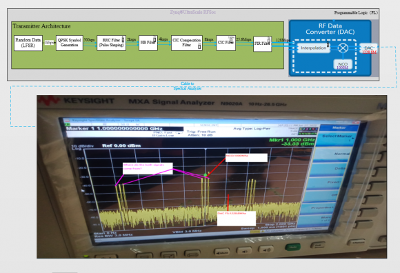
When I observe the acquired signals from MXA Spectral Analyzer and foud that there are the both other signals On either side of the carrier signal(including image carrier signal).
where do the both signals come from? any advice??
Thanks in advance and have a nice day!
Best Regards.
Comly

Frankly, I can't even read any of the images -- they're too fuzzy. And the scope shot is at a "bad" angle for trying to make any sense of the screen (I don't have that tool, so I have no insight into what it might represent). From my limited experience with spectral analyzers, I do know that some are easily overdriven and will then produce unexpected results like signal artefacts.
Hello,
I don't know enough about SDR to help specifically with algorithm issues. And it seems like there are a lot of processing steps, that could introduce/contribute to these unexpected signal components. But is there any way to dump data before each steps, starting with the incoming signal. If it were me, I'd dump that data and run it through an offline FFT or DFT (MATLAB or C version), to examine the signal content. Generally, the more data points, the better, for spectrum resolution, etc. Power of 2 makes it easier to run FFT, i.e. 8192, 16384 ... I've even gone up to 131072, if having the capability to store/dump that amount of samples. And repeat that exercise, until the unexpected signal components appear.
Regards,
Robert
Another idea is to examine all configuration items for the signal generation, acquisition, algorithm and overall processing, with a fine tooth comb. Review, and re-review, trying to see where the configuration may have been done improperly, to introduce such components, whether actual or some artifact resulting from mis-configuration or aliasing. Also, if you can take the absolute simplest case of input, versus expected output, to debug initially, would help. Is there a such thing as a single frequency input to SDR, i.e. 60 Hz or whatever, so we'd know exactly where it should appear in the resulting output.
Regards,
Robert
Hi Robert,
Thank you for the good advice.I'm doing it using method of bisection.and find out which part comes from?The backend RFDC or the frontedn filters?
Best Regards.
Comly

I don't see post DAC filter. Expect images (aliases) in analogue domain that follow sinc function.
Even a single tone passed to DAC will have infinite images that drop in amplitude towards a null at Fs or its multiples.
edit: if you mean those central three peaks but expected one peak then either your random data is not random or your processing got wrong


