


How to create the equivalent lowpass signal of a multi-tone signal
I know I have been asking a lot about amplifiers, this will be the last question, I promise!
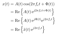
So, any single-tone signal can be represented as an equivalent lowpass:
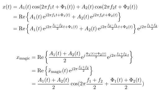
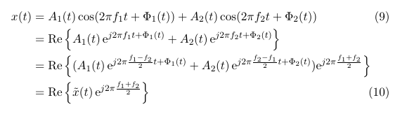
I am, however, interested in a two-tone signal. Is there a way of representing a two-tone signal with one equivalent lowpass? I was trying to get to the answer myself, this is what I have so far:
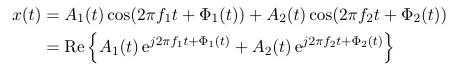
But this would give me two equivalent lowpass signals, right?

With the phase variation (your \(\Phi\)), I don't think that it's valid to take just the real part of your low-pass expression -- but that's a nit.
For your two-tone question, take your expression for \(x\left(t\right)\) and re-cast it as a signal centered on \(\frac{f_1 + f_2}{2}\). Then do the same magic that you did for your one-tone example.
And feel free to keep asking questions. You're clearly learning, and it's not like anyone is holding a gun to our heads to give you answers.
Is this, what you mean by re-casting:
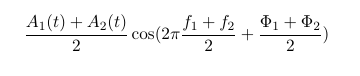
Is this still the same two-tone signal then?
I'm going to put on my Socratic Method hat and turn your question around: is it still the same two-tone signal? Can you show that it is or is not by grinding through the math?
Sit down with a pencil and paper and see.
I don't know how to show that these signals are not equal, but here's my intuition:
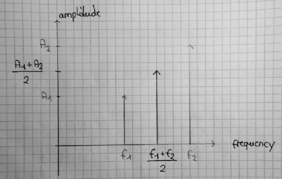
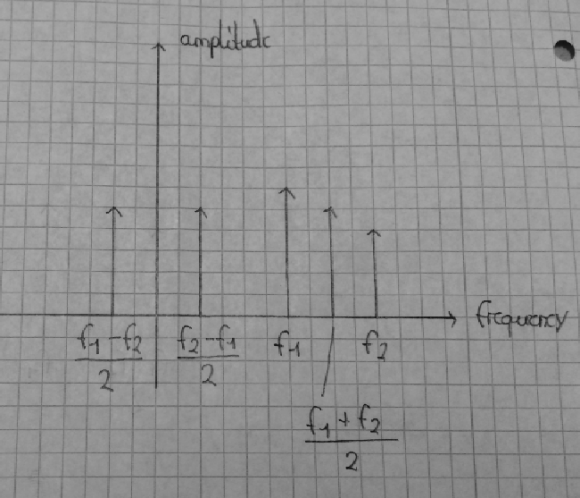
The original two-tone signal consists of two cos-waves at different frequencies. The spectrum would therefore have signal components at frequencies f1 and f2 (see the pencil lines in my sketch).
The other signal, however, has only one signal component - that makes it a single-tone signal. It is drawn a bit darker in my sketch.
So, I am back at my original question: Is there a way of transforming a two-tone signal into an equivalent lowpass signal? - There has to be a way!
Hint:
LaTeX has defeated me.
exp(j * w_1 * t) + exp(j * w_2 * t) =
(exp(j * (w_1 - w_2)/2 * t) + exp(j * (w_2 + w_1)/2 * t)) *
exp(j * (w_1 + w_2)/2 * t)
Trivial, yes -- but it brings your two tones down to baseband.
Thx Tim, I feel like I am slowly getting there, but I'm not quite there yet.
So from your nice exponential formulas trick, I see that you are basically just shifting the frequency components from passband back to baseband:
But, as you can see in my sketch, the difference to the passband components is the amplitude!
I still don't see how to simplify my sum of two exponentials to just one exponential (see last row of x(t)). I am trying to simplify everything to just one exponential in the equations following x_magic. But it doesn't seem to be the final solution.
I am pretty sure it is possible, because Matlab can do it:
When I consider a two-tone signal x(t), I can take the absolute value of the analytic signal and that should be equal to the equivalent lowpass of x(t):
x_lowpass = abs(hilbert(x));
I said this before, but apparently too weakly: you absolutely positively cannot shift an arbitrary RF signal from a frequency somewhere within its bandwidth down to baseband while retaining only the inphase component (i.e., by keeping only the real part). You MUST do it in quadrature.
It's a bandwidth thing. A real signal mirrors all of it's information around 0Hz, so a 0-5kHz signal at baseband has 5kHz worth of information. If you consider a 1.995MHz - 2.005MHz signal, it can have up to 10Hz worth of information -- but if you shift it down with a 2.000MHz carrier in only one channel, you'll end up with a signal that goes from 0-5kHz, and you'll lose half of the potential information. This is what's happening to your two-tone signal.
Note that, because your original example had a time varying phase (\( \Phi \left( t \right) \)) and a time varying amplitude, it also has different information contained above and below the carrier. So -- as I said, but apparently too weakly -- you can't do the down-conversion while only retaining the real part.
Also note that you can shift a signal down with a carrier outside it's bandwidth -- for my example, if you had a carrier at 1.995MHz you could theoretically get a signal at baseband with all the information, although in practical terms you'd probably be better off with a 1.990MHz carrier -- or doing quadrature downconversion.
Ok. Sorry, I'm a little slow on this topic.
If I understand correctly, by shifting a bandpass signal down to baseband, half of the information will be in the negative frequency domain (whatever that may be in reality), and therefore is considered 'lost'. So apparently, this is not an option.
I hope it is clear, what I want (I probably just don't understand your answer well enough to see how it is done):
I want to represent a two-tone signal in terms of its complex envelope (equivalent lowpass),such that I can consider just one amplitude and one phase, that I can change.
In this link on page 75, the concept that I want to make use of, is described. But of course, only for a single-tone signal.
Ah. Look at equation 3.4.2. Equation 3.4.1 (which is what you stated in your original post) ends with \[ x\left( t \right) = \Re \left \{ \tilde x\left(t\right) e^{j \omega_c t} \right\} \] but then you extract just the \( \tilde x \left( t \right) \) -- and \( \tilde x \) must be complex for the math to work.
So, he's assuming that you just know. Or that some teacher will set you straight. Alas, only some anonymous guy on the Internet has done so, and you have no way of knowing that I'm not just some really clever chat-bot running on an illicit computer in someone's dorm room.

The original math was a little terse for me. But I read it anyway...
It occurs to me that the definition of the question leaves a bit to be desired.
I would say this first:
"It is not possible to represent a single-tone signal as anything but what it is". So an "equivalent lowpass" (whatever THAT is), would seem to be out of the question.
But that's a bit too harsh perhaps. Consider this:
A single tone REAL signal (i.e. a sinusoid) is represented in frequency by two components: one at positive frequency and one at negative frequency. This affects the diagrams that have been presented. They are only half the picture.
Now, is the objective to
1) TRANSLATE the frequency domain signal .. (like a time delay would appear in time)?
or is it to
2) SHIFT the frequency domain signal so that the components are:
2.a) moved by a constant frequency amount?
or
2.b) moved by a proportional frequency amount?
Examples:
1) REAL Frequency deltas at 1kHz and -1kHz are translated down by 900Hz to 100Hz and -1,900Hz.
I don't recall seeing this in practice and the time-domain result will surely be complex. But, it's mathematically tenable.
2.a REAL Frequency deltas at 1kHz and -1kHz are shifted down by 900Hz to 100Hz and -100Hz. And if there were additional components such as 1.1kHz and -1.1kHz, they would be shifted down by 900Hz as well to 200Hz and -200Hz. This is likely the most common thing to do. Note that the frequency (and phase) relationship between the two sinusoids remains the same. I think this is what you must mean as an "equivalent lowpass".
2.b) REAL Frequency deltas at 1kHz and -1kHz are translated down by a factor of 10 to 100Hz and -100Hz. And if there were additional components such as 1.1kHz and -1.1kHz, they would be translated down by a factor of 10 to 110Hz and -110Hz. I don't know that I've ever seen this but it does match the words "frequency multiplication". Note that the frequency relationship between the two sinusoids is changed and phase loses meaning relative to the starting point at least.
So, let's stick with 2.a. One needs to be mindful that the translation frequency is important and determines the usefulness of the end result. Double sideband AM comes to mind: Typically you start with an audio signal, translate it up to a carrier frequency and later translate it back down by the same carrier frequency so it is centered at zero. In this case, phase matters because the "positive" frequency part goes into the negative frequency range and the "negative" frequency part goes into the positive frequency range and the two overlapped add in phase in important ways.
But, if you choose, you could translate it down so that all of the components show up above zero frequency (and equally below zero frequency). That's not your grandfather's AM demodulation but it does have lower bandwidth and could be useful. And, your forumlation might be viewed as a type of double sideband supressed carrier where the carrier frequency amplitude is zero.
Back to your original question then:
You don't have a term "fc" i.e. the "carrier frequency" at all. As Tim pointed out, you might choose (f1+f2)/2 - the midway point. Then, if you translate (properly) by this amount you will get frequency terms near zero frequency at:
f1-(f1+f2)/2 + f2-(f1+f2)2
useful identities for frequency shifting are:
f(t) <> F(w) where "<>" means a Fourier transform pairing.
f(t)*ejw0t <> F(w-w0)
and f(t)*cos(w0*t) <> (1/2)*[F(w+w0) + F(w-w0)]
Then, by superposition, if there are two terms: f1(t) <> F1(w) and f2(t) <> F2(w), then
[f1(t) + f2(t)]*cos(w0*t) <> (1/2)*[F1(w+w0) + F1(w-W0)] +(1/2)*[F2(w+w0) + F2(w-W0)]
And, if you choose the midpoint in frequency as Tim suggested, you would have w0=(w1+w2)/2 giving:
[f1(t) + f2(t)]*cos((w1+w2)/2*t) <> (1/2)*[F1(w+(w1+w2)/2) + F1(w-(w1+w2)/2)] +(1/2)*[F2(w+(w1+w2)/2) + F2(w-(w1+w2)/2)]
Of course, this includes the sum AND difference (lowpass) frequency components so you might simplify to:
(1/2)*[F1(w-(w1+w2)/2)] +(1/2)*[F2(w-(w1+w2)/2)]
then consider that (where d() is the Dirac or delta) and that F(f) is purely Real for sake of simplicity:
F1(w) = (A1)/2[d(w1) + d(-w1)]
F2(w) = (A2)/2[d(w2) + d(-w2)]
Well, I did it in a hurry so I hope it's all correct....
Reading the book pages the OP referenced, the goal is to downconvert the signal from being centered on a carrier to being centered on 0Hz. Or, probably, to get the reader ready to understand that you can do so.
Exactly - and that's how I ended my post... I believe.
Uh, I may not have read all the way to the end?
wow, this is so much input, thank you guys so much!
This should be the correct result then:
The equivalent lowpass, or complex envelope representation is often used to represent narrowband bandpass signals. But what exactly are the benefits of having a baseband instead of a bandpass signal?
I can extract the amplitude and the phase from the complex envelope representation. This can easily be done with abs() and phase() command in Matlab. I think it is not so easy with the original bandpass representation. Is this the only reason to use a complex envelope?


