


Hi,
I would like to get your advice on a simple question - how to implement 2nd order IIR filter with fixed point arithmetic operations (VHDL). The filter coefficients are:
a1=-1.87326115958843, a2=0.877280561373008, b0=1, b1=2, b2=1.
The question seems quite basic, but what I want to know is how to represent coefficient a1 in fixed point and still get same frequency response. I have tried to divide a1 by 2 and the simply add the result 2 times, but I get overflow=> errors.
Any ideas?
Thank you,
Dimitar Marinov

This is really a VHDL question. The mind-set that you want to use is to ask the question "how do I get the desired effect in my arithmetic operations?".
In C, assuming 32-bit data paths, you could do something like the code snippet below. Note that the code snippet contains all sorts of errors and omissions -- I'm just trying to give you a starting point here. Note also that if you do the equivalent thing in VHDL that a bone-headed synthesizer would create tons of excess gates -- I'm assuming that if you do something like this you'll verify that your synthesizer is doing a good job of optimizing out any excess, in much the same way that a good C compiler would make the code below far more efficient than it would be if it were just translated straight to assembly from the code.
const int64_t a1 = (-1.87326116) * 32768;
const int64_t a2 = ( 0.87728056) * 32768;

int64_t y = 0;
int64_t x1big = x1; // assume x1 is 32-bit
int64_t x2big = x2;

y = x1big * a1 + x2big * a2;

int32_t returnval = y / 32768;

One thing you can do is called "filter scaling." From my DSP textbook, if the passband gain of your IIR filter is GIIR then you can reduce that gain to be:
GIIR-scaled = G1G2GIIR.
The factors G1 and G2 are less than one in value and are shown in the following figure of a 2nd-order IIR filter.
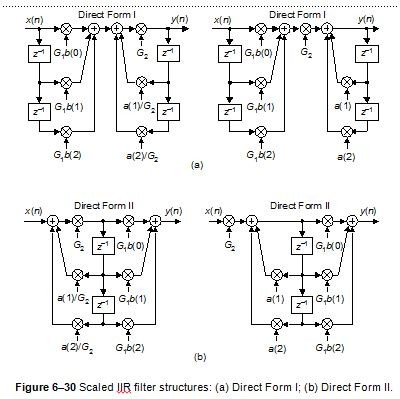
The general philosophy is to choose factors G1 and G2 keeping all network-internal sample values as large as can be accommodated by the filter hardware registers. The problem is: there's no simple way to determine the values of G1 and G2. The suggested procedure is to select one of the figures implementations and apply the expected input signal to the filter. Next you experiment with different values for gain factors G1 and G2 until the final filter gain, GIIR-scaled, is an acceptable value. Following that, you select an alternate filter network (in the above figure) and experiment with different values for gains G1 and G2 to see if you can improve on the previous scaled-filter network.
Good Luck.

Thank you Rick,
I thing this is the solution I was looking for.
Best regads
Hi,
You're most welcome. If you wish, let us know how things work out for you.
You have to consider two things : the data width and the format. For example, for 32 bits width, you can have Q1.31, Q2.30, Q3.29, etc...
The more fractional bits (right part of Qx.y), the nearer you will be from floating point accuracey. Since I see that you have a 1.xxxxx value in the coefficients, you will need at least a Q2.xxx format.
Then you have to consider the biggest result you get for any operation in the data stream. You probably saturate because you don't have enough integer bits (the left side of Qx.y format)
Benoit
Hi,
I am writing with my solution to the problem but first I have some details to clarify:
1. I get the data from audio codec as two's complement (24 bits - 1 sign bit and 23 fraction bits).
2. The filter is part of 50th order cascaded IIR filter designed in MATLAB. When designing IIR filters in fdatool the output is 2 matrices - one with the coefficients and one with the gain values between each stage.
So the solution ti his problem was quite simple - scale the input by the corresponding gain value, which in this case is ~0.001.


