


90 Degrees Shift of Digital Signal
I'm designing an electricity meter from scratch. I'm already measuring with great accuracy the active energy but I'm facing some problems with the reactive energy (RE).
In order to make the calculation of RE I need to shift the voltage signal by 90 degrees. I succesfully did it using a second-order low-pass digital filter of the following form:
This works good for 60Hz (My nominal frequency). But as a requirement I need to be able to measure with accuracy the RE from 50Hz to 70Hz. Since the filter is frequency-dependent I had to create a way to calculate the signal frequency (or period) and recalculate the filter alpha based on it.
I'm fiding the signal period with good accuracy (1/256 of the sample interval) using interpolation by succesive approximation. I found the value of alpha experimentally for 50 to 70hz and then used excel regression tool to find a 2nd-order polynomial approximation of the alpha formula. The problem is that this equation can lead up to 9% of error in the alpha, and the RE calculation is very sensitive to this.
Another problem I'm facing is that, even when I find the correct alpha for a given frequency, the new 90 degree shifted signal has different amplitudes for different frequencies. This is, the 50Hz 90deg shifted signal and the 60Hz 90deg shifted signal have different maximum values. The filter has different amplitude response for the same phase shift, on different frequencies. Because of this I'll have also to create a way to compute on-the-fly my reactive energy amplitude constant.
What I'd like to know from you, more experienced dsp engineers, is if I'm going on the right direction here, or should I try something different to shift the voltage signal? A different filter topology maybe? Really, any hints are welcome. On the internet I have found about the #HilbertTransform, but it sounded expensive to compute. (I'm using a low-end 16-bit microcontroller).
If I implement an hilbert-transform using IIR filters, the phase shift will be 90 degrees from the original frequency for all frequencies? (My requirement is from 50 to 70Hz). The amplitude response will also be the same? (I mean the maximum value will be the same for different frequencies?).
Please let me know if there's any more information I can give you to help me with this. Thanks!!

By filtering a sinusoid to shift it 90 degrees, you are effectively already doing a Hilbert transform at that frequency. You are using a real pole to provide 45-degrees phase shift, which requires careful tuning of the pole and gain compensation. Each of your one-pole smoothers can be viewed as a first-order Butterworth lowpass. The phase shift reaches 45 degreesat the -3dB point, so your gain correction should be sqrt(2) when alpha is correctly tuned. (It would be nice to see the complete computation you are using, although we can probably guess it. I can imagine formulations in which the gain would cancel out.)
Note that your filter is easier to see in the analog s plane, where each pole location should be s = -2*pi*fc, where fc = 60 Hz (or 50 or 70). You can use bilinear() in Matlab or Octave to convert this to alpha for your sampling rate, or just do a bilinear transform by hand: s = g * (1-1/z)/(1+1/z) where g is chosen to map fc exactly on the frequency axis.
In any case, it looks like what you'd prefer is an allpass filter that delays 90 degrees over a range of frequencies including 50-70 Hz, instead of having to use a different alpha for every analysis frequency.
Here is a paper on designing a filter that will give phase quadrature over a wide frequency range:
@conference{abel2010an,
title = {An Infinite Impulse Response (IIR) Hilbert Transformer Design Technique for Audio},
author = {Abel, Jonathan S. and Berdahl, Edgar and Harris, Daniel},
booktitle = {Audio Engineering Society Convention 129},
month = {Nov},
year = {2010},
url = {http://www.aes.org/e-lib/browse.cfm?elib=15680}
}
Your analysis is completely correct. That's exactly what I did: designed a simple analog low-pass filter and then used its digital counter-part. I cascaded two stages so the magnitude loss would be smaller.
The problem, like you said, is that this kind of filter is very sensitive to its alpha value. Any small change in frequency throws my reactive energy accuracy off-limits. That's why I'm looking for an alternative.
One way to solve this is to create a huge Look Up Table with the alpha-values for different frequencies. But this would be a big waste in memory. I'm not sure yet I'll have the resources for this.
The all-pass filter that you mention would give me a lock at 90º phase shift for all frequencies? What about its magnitude response? You have any suggestion about material for this?
I can show you more of my computation. There's any part you might be particularly interested?
Thanks!

"The all-pass filter that you mention would give me a lock at 90º phase shift for all frequencies?"
NO! You absolutely, cannot, in this world, get a 90 degree phase shift across the board with physically realizable filters. Only in a universe that allows you to see into the future, or an application that lets you wait an infinite amount of time for an answer, could you do this.
You really need to define your problem more fully -- what frequency range do you really care about (i.e., when you say "all frequencies" do you mean DC to light, or do you mean something else)? What do you intend to do with harmonic energy? What precision are you looking for?
When I say all frequencies I mean my range requirement as stated in the original post. This is: 50Hz to 70Hz.
I'm looking for 0.5% accuracy of active and reactive energy. Active energy is already working inside this limit, and reactive too (if locked at 60hz). My problem is to find a way to obtain the reactive energy that will work for my frequency range and that will be feasible in my low cost system.
The problem with the method I've been using (second order low-pass filter) is that I need to modify the filter alpha and the reactive magnitude calibration constant every time the frequency changes. One solution is to use lots of memory to save the values of those constants in memory for each freuqnecy. Other way looks to be construct kind of HT method.
Edit: about harmonics, I want to remove them. But for this I believe I can add a simple low-pass filter in voltage and current to remove it.
Yes, low-pass filtering should remove harmonics; just design your filter for a cutoff somewhere between 70Hz and 100Hz (2nd-harmonic of 50Hz), and bear in mind the anticipated level of the harmonics. However, it'll also have strange responses to the frequency wobbling -- do you know how steady the frequency will be?
Honestly, I'm not sure. I believe it should be steady. On the input it will be connected to the real power-line, I mean from the electric utility. The output can be any load.
Then you're probably fine. You might want to check with your sales department, though -- in most places in the US you can run a clock off of the power line, but in some places in the world (indeed, in a few places in the US), the "electric utility" is a diesel engine connected to a generator, right down the block, and operated by the drunken brother in law of the local political boss. In that case, frequency variations could be rapid.
The question is -- do you want to be accurate in that circumstance, or do you want the product literature to employ some hedging?
To answer your actual question: yes, if you could somehow implement a Hilbert transform using an IIR filter, then the phase shift would be 90 degrees from the original frequency for all frequencies. Unfortunately, implementing a true Hilbert transform is physically impossible (even in that part of mathemagic land that you can access from inside a processor). The reason for this is that a true Hilbert transform requires input from the future (it's non-causal), in requires input from an infinite time in the future, and its impulse response has singularities.
Assuming that you can just operate at the power line fundamental frequency (see my other post), what you want to seek to do is to either come up with a pair of complimentary filters whose gains at each frequency multiply up to 1, with a consistent 90 degree phase shift between them (in phasor terms, you'd say that the gains at each frequency multiply up to sqrt(-1)). Because power lines generally come with harmonics free of charge, you want to either band-pass filter your voltage and current signals before or as part of your filtering, or you want to make your filters' responses extend up in frequency, to whatever upper bound you want to consider.
An alternate suggestion, if you can assert that the frequency is steady enough (which presumes that you're not getting power from a cheap or badly maintained genset), is to phase-lock to the voltage, then just delay the current signal by 1/4 of a cycle. This ignores harmonics.
I may be missing something here, but I believe delaying the current would be the same problem as delaying the voltage, no? Both can vary in frequency. I have choosen to delay the voltage because the current signal is often smaller, so it would suffer more from magnitude losses.
I think I understand what you mean about comlementary filters, to always create two signals with a 90 degree locked delay between this. One of those signals would be voltage and the other the volt90deg. But if I do like this, the voltage signal will no longer be in phase with the current signal, and I need them to be to correctly calculate both, active and reactive energy. Is my understanding correct?
On the suggestion to delay one of the signals, the difference is that I suggested that you lock into the frequency with a phase-locked loop. As long as the PLL settles quickly enough compared to any changes in frequency of the power, a simple delay would shift the fundamental (but not any even harmonics) by 90 degrees (-90 degrees for half of the odd harmonics).
For the complimentary filters I'm suggesting that you filter the voltage and current both, solely for the purpose of getting your reactive power measurement.
Once again, you're not going to get a good measurement of the power factor as it is usually defined these days, because you seem to be ignoring harmonics.
If you need to shift your signal by 90degwhile keeping the mag unchanged then the digital hilbert tranformer is the right tool. Refer to Rick's blog he wrote a very nice summary on how to generate an analytic signal. Obviously you need a system with dsp capability that's inline with your target accuracy. But do not overestimate fir implementation complexity. Hilbert fir filter has nice features: half of the taps are null, the remaining ones have symmetry. The best is to perform a feasibility study using a dsp tool like matlab.
As mentionned below, the best is that you rethink your problem formulation and find a model that is suitable for your low cost system.
If you do go the Hilbert route, There are some simplifications you should keep in mind.
* Use an odd number of FIR taps. That way, you can get the delayed unshifted signal from the middle tap and the shifted signal's delay will be an integer.
* Every other tap coefficient is zero, so the computation less time consuming than it might first appear. On a good DSP, two octaves should be easy; for audio, you need a decade.
* If you shift the voltage, don't forget to delay the current to match. (If your HT has 11 taps, the current needs to be delayed by [11 - 1]/2 = 5.)
Jerry
If I understand correcly you mean from the middle of the HT computation I'll need to extract what would be my non-delayed voltage signal. And that to have the current signal in phase with it I'd have to delay it by 5 samples. Is this correct?
My only concern so far is that the HT might be too much for my system. But I'll give it a try, maybe with some optimizations I can get it working.
Do you suggest any material specific to what you said? Thank you!
You mean the HT is the best tool for the job, but probably it will be too much for my 16 bit microcontroller? I'm running at 12Mhz and need to do metering in 3 phases.
Anyway I agree with you, I'll try first in matlab, and I'll definitely check the blog post you mentioned. Thank you!

Hello TheCyrus. The blog that dhad referred to can be found at:
https://www.dsprelated.com/showarticle/153.php
Another blog that may be of some interest to you can be found at:
https://www.dsprelated.com/showarticle/192.php
Thank you for the links! I'll take a look!!

Hi @TheCyrus,
I don't have an answer to your question but I have no doubt a DSP guru will have some tips for you really soon.
I just wanted to point out that the forum system uses Mathjax so you can use TEX code for your equations. For example:
$$ volt_{45deg}[i]=(1-\alpha)volt_{45deg}[i-1]+(\alpha)volt[i] $$
The TEX code for this equation is:
$$ volt_{45deg}[i]=(1-\alpha)volt_{45deg}[i-1]+(\alpha)volt[i] $$
Thanks for using the DSPRelated forum @TheCyrus and good luck!
Thank you @stephaneb. I didn't about the TEX support here.
To rephrase things a bit, you're skinning a cat using method number 394, and you're thinking that you need a different knife to do the job correctly.
Might I suggest, instead, that you use cat-skinning method number 8?
If you calculate the total real energy (by integrating voltage and current), and then calculate the total apparent energy (by multiplying RMS voltage and RMS current), then the difference between the two is the apparent energy.
Note that I say "apparent" rather than "reactive" energy because the method that I outline takes harmonic currents and voltages into account, where the method that you're considering is really only valid for voltages and currents that are pure sine waves.
I don't know if this works within your requirements, but it's something to think about.
Correct me if I'm wrong, but your idea is for me to calculare Vrms, Irms, Active Power (P), Apparent Power (S) and then calculate reactive energy (Q) using the formula S = sqrt(P^2 + Q^2)?
That's an approach. The only problem is that I'd have to calculate many things that aren't really necessary to my application. (I only really need the active and reactive energy). But this might be the route to take.
Thanks.
Well, if you think about it, your 90-degree phase shifted signal isn't at all necessary to your application, so no matter what you do you need to compute intermediate results that you won't be presenting to the user.
And if you go the FIR Hilbert transform route, that gives you a signal that's phase shifted and delayed, so you have to hold old samples of the "unshifted" signal and pick the correct one out (this is actually a variation of my suggestion of two signals that are shifted 90 degrees from each other -- most people in DSP are so used to ignoring constant delays that they don't think of them very hard).
How do you intend to deal with harmonic energy?

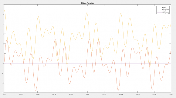
The Hilbert Transform's imaginary component doesn't shift everything equally by 90 degrees, I dont think?
I did a quick check in matlab, taking a function 'x' and doing the hilbert transfor, 'y'
Note, the blue plot is under the yellowish one...
The true (i.e., physically unrealizable) Hilbert transform does. Your Matlab Hilbert transform is, perforce, an approximation (you can tell this because you've physically realized it).
I have used HT with large number of taps in the past. I have tried with small number of taps (for the first time) for this application. I'm surprised to get a good gain accuracy with only 4 different taps !
I wanted just to check the gain error of a reduced complexity HT fir filter. I have designed a 17 taps filter using fdatool. The impulse response has only 4 non zeo different taps. I got a gain error smaller than 0.6mdB in your frequency band. This confirms for me that may be a simpler ht filter can still maintain good performance. That's why I encourage you to investigate further filter optimization if your problem still needs HT filter.
You mean you have succesfully used HT to calculate reactive energy? May I ask you what kind of microcontroller you have used?
I know that SOGI (Second Order Generalized Integrator) can generate a quadrature signal (90 degree shift). However, I've seen some numerical issues.
I'll take a look in this approach. Do you think this is feasible to use in a small microcontroller?

Hi ,
I have just joined the forum and found your problem with which I can help a bit . Here are my $0.02 :
First off : The other method advocated that you calculate Vrms, Irms, Active Power (P), Apparent Power (S) and then calculate reactive energy (Q) using the formula S = sqrt(P^2 + Q^2) is workable only for single phase systems , where the definition of Apparent Power is Vrms * Irms.....for Three Phase systems , the Apparent Power is derived from the KW calculated by direct multiplication of voltage and current samples AND KVAR (Q) calculated by multiplication of voltage samples with 90 deg. phase shifted current samples.There is an IEEE document out there which covers this...
This is where the Hilbert Transform comes in and that is the way to go...
Just like KW is to be derived from first principles , so is KVAR . There is a lot of difference in calculating parameters as we move from single phase to three phase . e.g. PF in a single phase system is defined as the ratio of KW and KVA where KVA is Vrms * Irms . However , as we go to three phase , the average of the three phase-wise power factors is not the system power factor ! You could have a situation where the phase-wise KVAR values ( which are signed ) have different signs , indicating that while reactive power is flowing in one direction in one phase , it could be flowing in the reverse in another .
So , the formulae to be used in three phase are as under :
a. Phasewise KW from first principles.( Unsigned positive values - we are not considering import/export of power yet ) . Add all three to get system KW.
b. Phasewise KVAR from first principles.( voltage samples multiplied by HT shifted current samples) . These will be signed values. Signed addition of three will give you system KVAR .
c. Sign of this system KVAR indicates whether system PF is lagging or leading . minus means leading.
d. System KVA from S = sqrt(P^2 + Q^2).
e. System PF from ratio of system KW and system KVA.
f. Integrate all three powers seperately to get three energies . KVAh = sqrt ( KWh^2 + KVARh^2) is flawed.
I can help with a code snippet where I am running the Hilbert Transform which works from 46 Hz to 63 Hz . Never checked for lower or higher than this....
Oh , I should mention that acheiving 0.5 accuracy on either KW or KVAR depends on the PF at which you want those . For KW , acheiving 0.5 will be be excruciatingly tough as you approach zero PF .
On KVAR , the errors will begin to get worse as you approach unity PF.But I'm sure you know this already !
We are using a small microcontroller and processing 16 bit ADC samples. Which microcontroller are you using ?
Also , These links might help :
Hello @dsprookie! Great post!
You are completely right about the calculations for three-phase meters. Indeed I'm still using my original approach, this is, a second-order butterworth digital filter.
What I did for it to work from 50-70Hz was to create a Look-Up Table with the alphas values for each 0.1Hz. I then calculate the signal frequency during execution and change the alpha accordlingly. It sure does work. But I feel it creates additional overhead and my calibration process is a little bit slower (since I need to calibrate the reactive amplitude too, because of the filter response).
About the errors for low power factors, I honestly didn't test my meter with very low power factors (well I tested it with 0PF, and it worked normally). I'll take a close look on this, for sure.
Currently I'm experimenting with two MCU's. MSP430F5340 (12 bits ADC) and MSP430F6736 (24 bits for current and 10 bits for voltage). Obviously the later one is better. But also more expensive.
I'm very interested in looking at your code snippet, for the Hilbert Transform. I designed one, using MATLAB, with 11 taps. But found out it was not providing 90degrees shift for my necessary frequency range. That's why I designed the LUT method. I'm curious to see your method. Can you share it with us?
Thank you!!
Sorry for delayed response as I was travelling . Will post the code ASAP......
Here is the code snippet..I used the insert file icon...As I looked at it , i see that we too have a look up table for different frequencies..maybe our approach is the after all the same as yours ( sheepish grin )...
ADC.cI don't have too much experience in 16-bit processors. Thus, probably I can't make the comment on your concern.


