


Graphical or mathematical depiction of asymmetric spectrum of complex baseband signal around 0 Hz.
In a lot of online lecture notes, it is usually assumed that the shape of the spectrum for a complex baseband (IQ) signal, in the form i(t)+j*q(t), can be asymmetric around 0 Hz. (Example: R. Lyons' excellent Quadrature Signals Tutorial) To try to prove this to myself, I postulate that i(t) & q(t) are both real signals and q(t) is the Hilbert transformed signal of i(t). Then, q(t) is multiplied by "j" and is added to i(t). This mathematical manipulation will result in either a positive frequency only baseband spectrum or a negative frequency only baseband spectrum. This is kind of like a baseband version of depicting a single-sideband spectrum on either side of 0 Hz.
However, I am unable to show or derive how to get an asymmetric spectrum in BOTH the positive & negative frequency sides around 0 Hz at the same time.
Is there anyone who can help me or show me a book or online resource that shows at least some diagrams depicting how to create asymmetric spectrum around 0 Hz in both + & - frequencies?
Thank you in advanced.
Regards,
Chi Shum
simplest possible waveshape, complex sinusoid with a phase angle:
x=(1+j1)*exp(j*phi*n)= sqrt(2) exp(j*phi*n+j*pi/4)
Hi fred_harris,
Thank you for replying. I think my problem is better depicted if I create a diagram such as the one inserted here. In your explanation, the amplitude A of your complex exponential A*exp(j*phi) is also complex, but can be manipulated as a real amplitude with a phase shift of pi/4. I agree with that. But how would I draw this with respect to the illustration I have attached to show that the spectrum is asymmetric w.r.t. to 0 Hz or even w.r.t. upconversion to omega_LO? What am I not seeing? Thank you for your time!

Not sure what you are asking but:
Spectrum of (I) alone is always symmetric. Of (Q) alone is always symmetric. Of (I +jQ) as one signal could be asymmetric.
I alone is real, Q alone is real. I+jQ is complex.
do fft then plot power

Hi kaz,
Thank you for responding to my question. Perhaps my question may be better explained with the illustration I have inserted here. I understand that i(t) & q(t) are symmetric by themselves and I have shown them to be in the picture. And when I upconvert to omega_LO, it'll look like a complex signal c(t)=i(t)+j*q(t) shifted in frequency to +omega_LO & c*(t) to -omega_LO. But my drawing seems to reflect a symmetric complex signal about omega_LO. In other words, c(t) as a baseband signal is symmetric around 0 Hz. What do I need to know to depict a scenario where c(t) is asymmetric about 0 Hz or omega_LO? Thank you for your time.
If your baseband signal is upconverted it just changes frequency centre from dc to new centre. This does not change its symmetry. Your baseband signal must be asymmetric to stay as such once upconverted. In other words your baseband signal must be complex and dseigned as asymmetric.
For example You can apply complex filter on complex baseband then upcnvert it. Or have a real signal of 5MHz bandwidth symmetric around dc then upconvert it to Fc. Then add another real signal at say 10MHz andwidth and upconvert to other side of fc then add up both to get 5MHz on one side of fc and 10MHz on other side.
Now you get asymmetry around fc. If you downconvert to dc it will stay asymmetric with 5MHz on one sode of 0 and 10Mhz on other side assuming there is enough gap.
Hi Kaz,
Thank you for your answer. Your concept of asymmetric spectrum can be generated by using single-sideband modulation for two different signals. Signal A with bandwidth A would be SSB modulated on the high side of Fc & signal B with bandwidth B would be SSB modulated on the low side of Fc.
Thanks again. I appreciate your inputs.
By the way in -say- QPSK modulator the I & Q are generated from stream by some arbitrary selection e.g. even bits seen as I and odd as Q. In other words there is nothing I/Q here in terms of phase.
The I & Q are mixed with Fc in a complex multiplier. The output is asymmetric complex around Fc and around zero.
I = randsrc(1,1000,[1 -1]);
Q = randsrc(1,1000,[1 -1]);
Fc = exp(j*2*pi*(1:1000)*.1);
I = filter(fir1(100,.1),1,I);
Q = filter(fir1(100,.1),1,Q);
IQ = complex(I,Q).*Fc; %u/c to Fc
IQ_dc = IQ.*exp(j*2*pi*(1:1000)*-.1); %d/c to zero
Thank you for your inputs!
Maybe think of it this way: a purely real signal has a spectrum that is symmetrical on the real axis and anti symmetrical on the imaginary. A purely imaginary signal has a spectrum that is symmetrical on the imaginary axis and anti symmetrical on the real axis. Any asymmetrical signal can be described as the sum of a symmetrical and assymetrical signal

Hi dszabo,
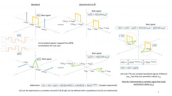
Thank you for your answer. I believe you may have unlocked the concept in my head regarding the fact that an asymmetric signal can be made from the sum of a symmetric & asymmetric signal. I have created a diagram of my understanding of IQ modulation from baseband to RF in a typical transmitter. I start with two real signals, i(t) & q(t), that are mapped from some random bit-stream into an 8PSK constellation. I upconvert them to +/- omega_LO in an IQ modulator. The final output, s(t), can be depicted as (1/2)*c(t)*exp(j*omega_LO*t) + (1/2)*c'(t)*exp(-j*omega_LO*t), where c(t)=i(t)+j*q(t).
My problem is that this complex baseband signal, c(t), is symmetric about omega_LO. In other words, c(t) is symmetric about 0 Hz if demodulated back to baseband. I don't know what to do to draw a situation where c(t) may look asymmetric about 0 Hz or omega_LO. One potential solution is to make q(t) into some form of a sine function while i(t) is in cosine function format. This method follows similarly to a single-sideband modulation method. However, I am not sure if this is a correct way of implementing an asymmetric spectrum signal. One will not always have a q(t) that is a sine function & i(t) in cosine function.
I can certainly see that if I make q(t) asymmetric, then c(t) is asymmetric. Do DSP and comm systems engineers make asymmetric baseband signals?
What am I missing in my knowledge? Thank you for your time.
Thanks for the plots, I think I see where you are getting tripped up. You spec’d both i(t) and q(t) as real, but you have depicted their frequency transforms, I(jw) and Q(jw), as also being purely real, which I am certain you didn’t mean to do.
The only way to get plots like the ones you drew would be if both i(t) and q(t) are symmetrical around t=0. In your case, you should be drawing both I(jw) and Q(jw) as having anti symmetrical imaginary components as well as symmetrical real components.
Hi dszabo,
You're correct. I did not remember what the Fourier transform is doing for a time domain signal with odd symmetry (sine), even symmetry (cosine), and arbitrary function with no symmetry. The I/Q signals from baseband are arbitrary signals with no odd or even symmetry and thus there are real & imaginary components in the frequency domain after Fourier transform.
Thanks for seeing through my hole in concept. I appreciate it.
No worries. I’m sure I wouldn’t have been able to help if I hadn’t made the same error at some point. Glad I could help. Cheers

Hello chiwang_shum. Here's the answer to your question. Open a new web browser page, go to the following web page, look at Figure 1, and then return here to read my reply to your question:
https://www.dsprelated.com/showarticle/753.php
In Figure 1 I show the input to be a cosine wave. But let's assume the input was a real-valued bandpass signal, centered at w_c radians/second (2+pi*f_c, where f_c is in Hz), and whose bandwidth is greater than zero Hz. The output of the Figure 1(b) network is a complex-valued signal centered at zero Hz.
And if the original real-valued bandpass signal's positive-frequency spectrum was asymmetrical, then the Figure 1(b) network's output spectrum (centered at zero Hz) would also have an asymmetrical spectrum.
Notice in Figure 1(b) that I did not add the i(t) and q(t) signals to produce the complex c(t) signal. In many "complex-signal" tutorials you'll see block diagrams where a real-valued i(t) signal and a real-valued q(t) signal are applied to a hardware adder to produce a complex c(t) signal. Those block diagrams are completely INCORRECT!!! chiwang_shum, in Figure 1's blog, scroll down and carefully read the section titled: "LYONS RANTING AND RAVING." The message in that section is VERY important.

Hi Rick Lyons,
First of all, your tutorials are the inspiration for me to draw these similar looking diagrams above. I enjoy your graphics and derivations very much. So thank you for your work on this site. Above, I have created a diagram of my understanding of IQ modulation from baseband to RF in a typical transmitter. I start with two real signals, i(t) & q(t), that are mapped from some random bit-stream into an 8PSK constellation. I assume i(t) and q(t) here are in a cosine function format and thus they are symmetric about the real axis. I upconvert them to +/- omega_LO in an IQ modulator. The final output, s(t), can be derived as (1/2)*c(t)*exp(j*omega_LO*t) + (1/2)*c'(t)*exp(-j*omega_LO*t), where c(t)=i(t)+j*q(t).
My problem is that this complex baseband signal, c(t), is symmetric about omega_LO. In other words, c(t) is symmetric about 0 Hz if demodulated back to baseband. I don't know what to do to draw a situation where c(t) may look asymmetric about 0 Hz or omega_LO. One potential solution is to make q(t) into some form of a sine function while i(t) is kept in a cosine function format. This way, q(t) has conjugate symmetry about the imaginary axis. This method seems to follow the single-sideband modulation method. However, I am not sure if this is a correct way of implementing an asymmetric spectrum signal. One will not always have a q(t) that is a sine function & i(t) in cosine function since these baseband information signals seem to be random versus time and thus uncorrelated from each other.
What am I missing in my knowledge to bridge the gap? Thank you for your time.


