


An Acoustic Echo Simulator
An acoustic echo is one of the simplest acoustic modeling problems. Echoes occur when a sound arrives via more than one acoustic propagation path, as shown in Fig.2.8. We may hear a discrete echo, for example, if we clap our hands standing in front of a large flat wall outdoors, such as the side of a building. To be perceived as an echo, however, the reflection must arrive well after the direct signal (or previous echo).
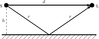 |
A common cause of echoes is ``multipath'' wave propagation, as
diagrammed in Fig.2.8. The acoustic source is denoted by `S',
the listener by `L', and they are at the same height ![]() meters
from a reflecting surface. The direct path is
meters
from a reflecting surface. The direct path is ![]() meters long, while
the length of the single reflection is
meters long, while
the length of the single reflection is ![]() meters. These quantities
are of course related by the Pythagorean theorem:
meters. These quantities
are of course related by the Pythagorean theorem:
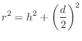
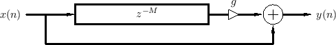
Figure 2.9 illustrates an echo simulator for the case of a direct signal and single echo, as shown in Fig.2.8. It is common practice to pull out and discard any common delay which affects all signals equally, since such a delay does not affect timbre; thus, the direct signal delay is not implemented at all in Fig.2.9. Similarly, it is not necessary to implement the attenuation of the direct signal due to propagation, since it is the relative amplitude of the direct signal and its echoes which affect timbre.
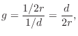
From the geometry in Fig.2.8, we see that the delay-line length in Fig.2.9 should be

Next Section:
Program for Acoustic Echo Simulation
Previous Section:
Reflection of Spherical or Plane Waves


