


Multi-Decimation Stage Filtering for Sigma Delta ADCs: Design and Optimization
During my research on digital FIR decimation filters I have been developing various Matlab scripts and functions. In which I have decided later on to consolidate it in a form of a toolbox. I have developed this toolbox to assist and automate the process of designing the multi-stage decimation filter(s). The toolbox is published as an open-source at the MathWorks web-site. My dissertation is open for public online as well. The toolbox has a wide set of examples to guide the user through the steps. Furthermore, there is a design template. I hope you all enjoy and get the best of it. I will be glad for your constructive feedback.
Overview
The Multi-Stage Decimation toolbox (MSD-toolbox) is developed in Matlab language. Designing a
decimation filter system starts with definite specifications such as the sampling
frequency ($f_s$), oversampling ratio (OSR), passband frequency ($f_{pb}$),
signal-to-noise ratio (SNR, regarded also as ADC resolution), in-band noise (IBN),
and a stimuli bit-stream from sigma delta modulator. It should be noted that, the transition
band-width ($\Delta f=(f_{sb}-f_{pb})/f_{sb}$) could be provided at the input specifications
instead of the passband frequency. The stimuli bit-stream permits accurate analysis for the
intra decimation stages.
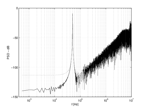
Moreover, involving the stimuli affords performing spectral analysis in addition to the
frequency domain analysis for the decimation filter. Whereas, involving the acceptable
tolerance in the IBN maintains additional flexibility for filter coefficient optimization.
The stimuli bit-stream can be imported from DelSig-toolbox [1],
DISCO-toolbox [2]. The MSD-toolbox has several routines and sub-programs
for calculating implementation parameters and performance evaluation.
The sub-programs and routines are based on state-of-the-art algorithms.
The essential routines are:
- Calculating $k$ and $M$ ($R_{T}(k,M)$)
- Calculating $h_k$ and $Q$ (P-M-E)
- Coefficient optimization (Optimization)
- Cost estimation (Cost)
For further details refer my dissertation can be found at DISSERTATION.
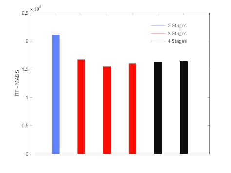
$k$ and $M$ Calculations
The optimal number of decimation stages and the decimation factor at each stage is calculated for
minimum computational effort ($R_T$), as given in
$$
{R_T} = {D_\infty }{f_s}\sum\limits_{i = 1}^k {\frac{{{M_i}}}{{\left( {\prod\limits_{j = 1}^i {{M_j}} } \right)\left( {1 - \frac{{{f_{sb}} + {f_{pb}}}}{{{f_s}}}\prod\limits_{j = 1}^i {{M_j}} } \right)}}}
$$
The problem is constrained for $k\in\lbrace2,3,4\rbrace$ and $M_k=2$ for even $M$'s, where $M$ is the
overall decimation factor (equivalent to OSR), $f_s$ is the sampling frequency, $f_{pb}$ is
the passband frequency, $f_{sb}$ is the stopband frequency, and $D_\infty$ is a function in
passband ($\delta_{pb}$) and stopband ($\delta_{sb}$) ripples, as depicted in
$$
{D_\infty } = {\log _{10}}{\delta _{sb}}[0.005309{({\log _{10}}{\delta _{pb}})^2} + 0.07114{\log _{10}}{\delta _{pb}} - 0.4761]
$$
$$
- [0.00266{({\log _{10}}{\delta _{pb}})^2} + 0.5941{\log _{10}}{\delta _{pb}} + 0.4278]
$$
where $k$ is calculated for minimum $R_T$ at distinct values of $M$.
Detailed analysis for optimizing the number of decimation stages and the decimation factor for each
stage is given in [3], [4], and [5].
$\delta_{pb}$ and $\delta_{sb}$ Calculations
The passband ripples ($\delta_{pb}$) and stopband ripple ($\delta_{sb}$) are calculated using iterative simulations preserving a predefined acceptable tolerance in the in-band noise (IBN). This is done by designing a single stage filter and tuning the $\delta_{pb}$ and $\delta_{sb}$, by defining a certain range or a set of discrete values. The $\delta_{sb}$ remains the same for all the $k$-stages. While, the $\delta_{pb_{i}}=\delta_{pb}/k$ for stage $i$.
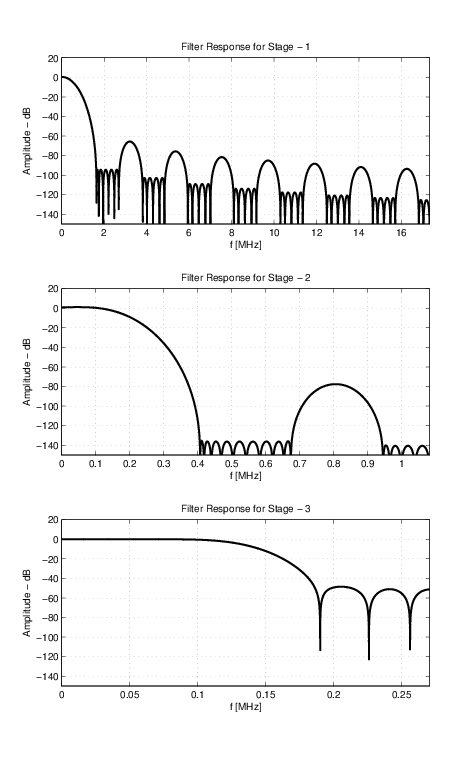
$h_k$ and $Q$ Calculations
The exact number of decimation stages and the dedicated decimation factor for each stage were calculated
in addition to the given design specifications, which sustain all the necessary parameters required for
calculating the filter coefficients ($h_k$) for each decimation filter stage employing the Parks-McClellan
Equiripple. Following the filter coefficient ($h_k$) calculation comes the quantization bit-width ($Q$)
calculation step in order to compute the scaled filter coefficient set ($\hat h_k$).
Initially, a set of parameters is calculated for each stage, such as baseband frequency ($f_B$),
passband frequency ($f_{pb}$), and stopband frequency ($f_{sb}$). The $f_B$ is calculated by
$$
{f_B} = \frac{{{f_s}}}{{2{\rm{OSR}}}}
$$
where OSR is the oversampling ratio and $f_s$ is the sampling frequency.
The $f_{pb}$ and the $f_{sb}$ are calculated by the equations given below.
However, the intermediate stopband frequency ($f_{sb_{i}}$) is calculated by
$$
{f_{pb}} = {f_B}(1 - \Delta f)
$$
$$
{f_{sb}} = {f_B}
$$
$$
{f_{s{b_i}}} = \frac{{{f_s}}}{{\prod\limits_{i = 1}^k {{M_i}} }} - {f_B}\\
$$
FIR filter has distinct implementation types, such as standard FIR (FIR), half-band (HB), and multi-band (MB)
types. The FIR filter implementation type affects the filter response and coefficients.
The Parks-McClellan Equiripple (P-M-E) algorithm is used to obtain the FIR filter coefficients ($h_k$)
for the predefined filter types except the CIC filter type. Subsequently, the required quantization
bit-width ($Q$) is calculated iteratively preserving minimum mean error (ME) or minimum increase in the
in-band noise (IBN).
Samples
References
[1] R. Schreier and G.C. Temes. Understanding delta-sigma data converters. IEEE press Piscataway, NJ, 2005.
[2] A. Buhmann, M. Keller, M. Maurer, M. Ortmanns, and Y. Manoli. Disco - a toolbox for the discrete-time simulation of continuous-time sigma-delta modulators using matlab. In Proc. Midwest Symposium on Circuits and Systems (MWSCAS'07), pages 1082--1085, Aug. 2007.
[3] R. Crochiere and L. Rabiner. Optimum FIR digital filter implementations for decimation, interpolation, and narrow-band filtering. 23(5):444--456, 1975.
[4] M. Coffey. Optimizing multistage decimation and interpolation processing. IEEE Signal Processing Letters, 10(4):107--110, 2003.
[5] M. Coffey. Optimizing Multistage Decimation and Interpolation Processing: Part II. IEEE Signal Processing Letters, 14(1):24--26, 2007.


- Comments
- Write a Comment Select to add a comment

Hi. Your definition of transition bandwidth being '(f_sb - f_pb)/f_sb' doesn't seem correct to me. Shouldn't that transition bandwidth
be '(f_sb - f_pb)/f_s' ?
Dear Rick,
Thank you very much for your reply.
Your remark is totally valid, however, I believe the definition of the $$\Delta f$$ is based on how it is used within the toolbox. The formulas used are:
$$f_b = \frac{f_s}{2OSR}$$
$$f_p = f_b(1 - \Delta f)$$
$$f_c = \frac{f_s}{OSR} - f_b$$
Let's consider the following simple numerical example, for $$f_s = 960kHz, OSR = 24, f_p = 18kHz, f_c = 20kHz$$.
$$\Delta f = (20-18)/20 = 0.1$$
$$f_p = f_b(1 - \Delta f) = 20(1 - 0.1) = 18$$
where $$f_b = \frac{f_s}{2OSR}$$
Hello ahmedshahein. I'm not able to understand you message here. You have used the phrase "baseband frequency" (f_b). I've never heard that phrase before from people when they talk or write about decimation filters. You defined that mysterious f_b variable in terms of an undefined variable that you call OSR. The phrase "oversampling ratio" makes me think of some kind of ratio (a fraction) being "something" divided by "something else." But I have no idea of what is in the numerator or denominator of that mysterious ratio.
Using non-standard (non-traditional) terminology makes it hard for a reader to understand your blog. Can you tell us in words what the phrases "f_b = baseband frequency" and "OSR" mean? Thanks.
Hi Rick,
The terminology shall be the standard one used for Sigma-Delta modulators (SDM). The OSR is the Over-Sampling Ratio, and the f_b is the base-band frequency for the SDM. The f_b is equivalent to the cut-off frequency of the decimation filter used for the decimating the SDM output. I hope it is more clear now.
Regards.

I think the blog is not about decimation in general but rather it is about a specific corner(that of SDM). So the title is a bit misleading.
Dear Kaz,
Thanks for your advice, I have renamed the title.
Regards.
To post reply to a comment, click on the 'reply' button attached to each comment. To post a new comment (not a reply to a comment) check out the 'Write a Comment' tab at the top of the comments.
Please login (on the right) if you already have an account on this platform.
Otherwise, please use this form to register (free) an join one of the largest online community for Electrical/Embedded/DSP/FPGA/ML engineers:


