Understanding the 'Phasing Method' of Single Sideband Demodulation
There are four ways to demodulate a transmitted single sideband (SSB) signal. Those four methods are:
- synchronous detection,
- phasing method,
- Weaver method, and
- filtering method.
Here we review synchronous detection in preparation for explaining, in detail, how the phasing method works. This blog contains lots of preliminary information, so if you're already familiar with SSB signals you might want to scroll down to the 'SSB DEMODULATION BY SYNCHRONOUS DETECTION' section.
BACKGROUND
I was recently involved in trying to understand the operation of a discrete SSB demodulation system that was being proposed to replace an older analog SSB demodulation system. Having never built an SSB system, I wanted to understand how the "phasing method" of SSB demodulation works.
However, in searching the Internet for tutorial SSB demodulation information I was shocked at how little information was available. The web's wikipedia 'single-sideband modulation' gives the mathematical details of SSB generation [1]. But SSB demodulation information at that web site was terribly sparse. In my Internet searching, I found the SSB information available on the net to be either badly confusing in its notation or downright ambiguous. That web-based material showed SSB demodulation block diagrams, but they didn't show spectra at various stages in the diagrams to help me understand the details of the processing.
A typical example of what was frustrating me about the web-based SSB information is given in the analog SSB generation network shown in Figure 1.
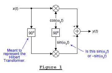
In reading the text associated with that figure, the left 90° rectangle was meant to represent a Hilbert transform. Well, in that case, the "90°" label should more correctly be "-90° because in the time domain a Hilbert transformer shifts a sinusoid by –90°." In Figure 1, assuming the rightmost 90° rectangle means some sort of 90° phase-delay element, then it's output would not be sin(ωct), it would be -sin(ωct). Ambiguous "90°" notation often occurs in the literature of SSB systems. (Reading Internet SSB material is like reading a medical billing statement; the information is confusing! So much of it doesn't "add up".) OK, enough of my ranting.
TRANSMITTED SSB SIGNALS
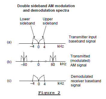
Before we illustrate SSB demodulation, it's useful to quickly review the nature of standard double-sideband amplitude modulation (AM) commercial broadcast transmissions that your car radio is designed to receive. In standard AM communication systems, an analog real-valued baseband input signal may have a spectral magnitude, for example, like that shown in Figure 2(a). Such a signal might well be a 4 kHz-wide audio output of a microphone having no spectral energy at DC (zero Hz). This baseband audio signal is effectively multiplied, in the time domain, by a pure-tone carrier to generate what's called the modulated signal whose spectral magnitude content is given in Figure 2(b).
In this example the carrier frequency is 80 kHz, thus the transmitted AM signal contains pure-tone carrier spectral energy at ±80 kHz plus sideband energy. The purpose of a remote AM receiver, then, is to demodulate that transmitted DSB AM signal and generate the baseband signal given in Figure 2(c). The analog demodulated audio signal could then be amplified and routed to a loudspeaker. We note at this point that the two transmitted sidebands, on either side of ±80 kHz, each contain the same audio information.
In an SSB communication system the baseband audio signal modulates a carrier, in what's called the "upper sideband" (USB) mode of transmission, such that the transmitted analog signal would have the spectrum shown in Figure 3(b). Notice in this scenario, the lower (upper) frequency edge of the baseband signal’s USB (LSB) has been translated in frequency so that it’s located at 80 kHz (-80 kHz). (The phasing method of SSB radio frequency (RF) generation is given in Appendix A.)
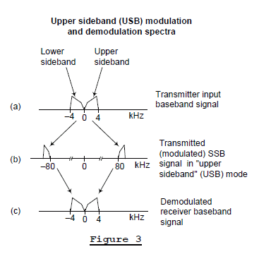
The purpose of a remote SSB receiver is to demodulate that transmitted SSB signal, generating the baseband audio signal given in Figure 3(c). The analog demodulated baseband signal can then be amplified and drive a loudspeaker.
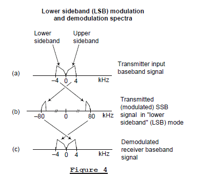
In a "lower sideband" (LSB) mode of SSB transmission, the transmitted analog signal would have the spectrum shown in Figure 4(b). In this case, the upper (lower) frequency edge of the baseband signal’s LSB (USB) has been translated in frequency so that it’s located at 80 kHz (-80 kHz). The baseband signal in Figure 4(a) is real-valued, so the positive-frequency portion of its spectrum is the complex conjugate of the negative-frequency portion. Both sidebands contain the same information, and that's why LSB transmission and USB transmission communicate identical information.
And again, in the LSB mode of transmission, the remote receiver must demodulate that transmitted LSB SSB signal and generate the baseband audio signal given in Figure 4(c).
WHY BOTHER USING SSB SYSTEMS?
Standard broadcast AM signal transmission, Figure 2, wastes a lot of transmitter power. At a minimum, two thirds of an AM transmitter's power is used to transmit the 80 kHz carrier signal which contains no information. And half of the remaining one third of the transmitted power is wasted by radiating a redundant sideband. So why are standard commercial AM broadcast systems used at all? It's because DSB AM broadcast receivers are simple and inexpensive.
In SSB transmission systems, 100% of their transmitter power is used to transmit a single baseband sideband. Thus they exhibit no wasted transmitter power as do AM systems. In addition, due to their narrower bandwidth, SSB systems can have twice the number of transmitted signals over a given RF range than standard double-sideband AM signals. The disadvantage of SSB communications, however, is that the remote receiver's demodulation circuitry is more complicated than that needed by AM receivers.
SSB DEMODULATION BY SYNCHRONOUS DETECTION
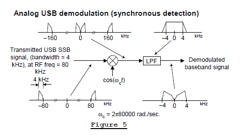
One method, sometimes called "synchronous detection", to implement the demodulation process in Figure 3 is shown in Figure 5. This method is relatively simple. In Figure 5 the analog RF input USB SSB signal has a carrier frequency of 80 kHz, so ωc = 2π•80000 radians/second. We multiply that input SSB signal by what’s called a “beat frequency oscillator” (BFO) signal, cos(ωct), to translate the SSB signal’s USB (LSB) down (up) in frequency toward zero Hz. That multiplication also produces spectral energy in the vicinity of ±160 kHz. The analog lowpass filter (LPF), whose frequency magnitude response is shown at the upper right side of Figure 5, attenuates the high frequency spectral energy producing our desired baseband audio signal.
A DSP version of our simple Figure 5 USB demodulation process is shown in Figure 6 where, for example, we chose the A/D converter’s sample rate to be 200 kHz. Notice the spectral wrap-around that occurs at half the sample rate, ±100 kHz, in the multiplier’s output signal. The digital LPF, having a cutoff frequency of just a bit greater than 4 kHz, serves two purposes. It attenuates any unwanted out-of-baseband spectral energy in the down-converted signal, and eliminates any spectral aliasing caused by decimation. The decimation-by-10 process reduces the baseband signal’s sample rate to 20 kHz.
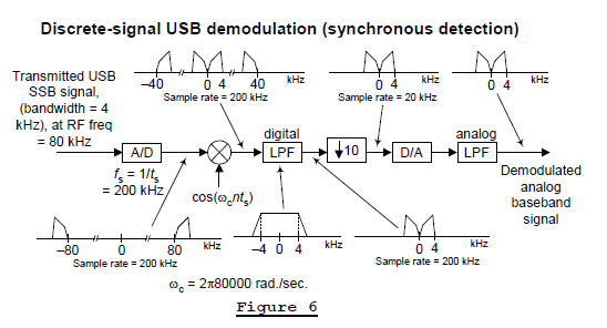
The analog LPF in Figure 6 attenuates the unwanted high-frequency analog spectral images that are produced, at multiples of 20 kHz, by the D/A conversion process.
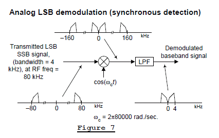
Returning to the analog demod process in Figure 5, had the incoming SSB signal been a lower sideband (LSB) transmission our analog processing would be that shown in Figure 7. The processing performed in Figure 7 is identical to that shown in Figure 5. So, happily, our simple ‘down-convert and lowpass filter’ synchronous detection demodulation process works for both USB and LSB transmitted signals.
THERE'S TROUBLE IN PARADISE
The simple demodulation process in Figure 7 has one unpleasant shortcoming that renders it impractical in real-world SSB communications. Here’s the story.
In the United States commercial AM radio broadcasting is carefully restricted in that radio stations are assigned a specific RF carrier frequency at which they can transmit their radio programs. Those carrier frequencies are always at multiples of 10 kHz. So it’s possible for us the receive one AM radio signal at a carrier frequency of, say, 1200 kHz while another AM radio station is transmitting its program at a carrier frequency of 1210 kHz. (Other parts of the world use a 9 kHz carrier spacing for their commercial radio broadcasts.)
[In the States, those commercial AM broadcast carrier frequencies are monitored with excruciating rigor. Many years ago while attending college I worked part time at a commercial radio station in Ohio. One of my responsibilities was to monitor the station’s transmitter’s output power level and carrier frequency, and record those values in a log book. Those power and frequency measurements, by law, had to be performed every 15 minutes, 24 hours a day!]
That careful control of transmitted signal carrier frequencies does not exist in today’s world of SSB communications. Think about the situation where two independent, unrelated, SSB Users are transmitting their signals as shown in Figure 8(a). User# 1 is transmitting a USB signal at a carrier frequency of 80 kHz and User# 2 is transmitting an LSB signal at a carrier frequency of 80 kHz. The operation of our simple ‘down-convert and lowpass filter’ demod process is given in Figure 8(b). There we see that spectral overlap prevents us from demodulating either of the two SSB signals.
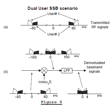
This troublesome overlapped-spectra problem in Figure 8(b) can be solved by a clever quadrature processing scheme. Here's how.
QUADRATURE PROCESSING TO THE RESCUE
Our dual-User SSB problem has been solved by a quadrature processing technique, called the “phasing method, which makes use of the Hilbert transform. See Appendix B for brief explanation of the Hilbert transform.
To explain the details of that process, let’s assume that a User#1 and a User# 2 have transmitted two sinusoidal signals whose baseband spectra are those shown in Figure 9(a). User# 1’s baseband signal is a sinewave tone whose frequency is ±3 kHz and it’s transmitted as an USB signal at a carrier frequency of 80 kHz, as shown in Figure 9(b). Let’s also assume that User# 2’s baseband signal is a lower-amplitude cosine wave tone whose frequency is ±1 kHz, and it’s transmitted as an LSB signal also at a carrier frequency of 80 kHz.

To understand the phasing method of SSB demodulation, we must pay attention to the real and imaginary parts of our spectra, as is done in Figure 9(b).
Figure 10 presents the block diagram of a “phasing method” demodulator.

What the Figure 10 quadrature processing does for us, to eliminate the overlapped-spectral component problem in Figure 8, is to generate two down-converted signals (i(t) and q(t)) with appropriate phase relationships so that selected spectral components either reinforce or cancel each other at the final output addition and subtraction operations. Let's see how this all works.
The real and imaginary parts of the transmitted RF spectra from the bottom of Figure 9 are shown at the lower left side of Figure 11.
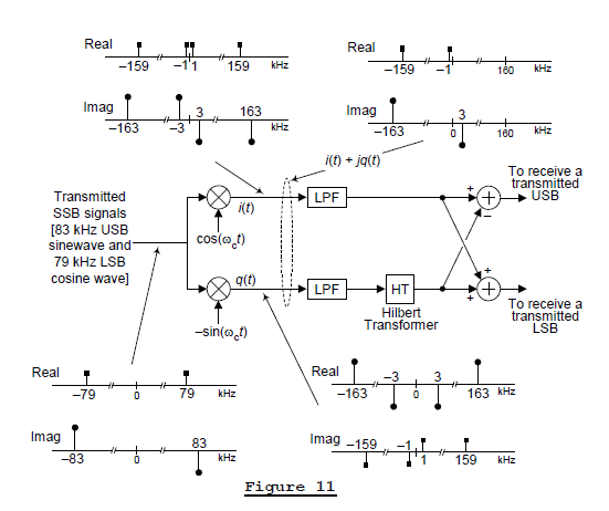
In the phasing method of SSB demodulation, we perform a complex down-conversion of the real-valued RF input, using a complex-valued BFO of e-j(ωct) = cos(ωct) -jsin(ωct), to generate a complex i(t) + jq(t) signal whose spectrum is shown at the upper right side of Figure 11. That spectrum of a complex-valued time sequence, is merely the demodulator's input spectrum shifted down in frequency by 80 kHz.
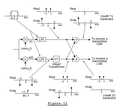
Figure 12 shows the spectra at the output of the mixers, the output of the Hilbert transformer, and the final baseband spectra. There we see that the output of the upper signal path produces User# 1’s baseband signal, with no interference from User# 2. And the output of the lower signal path yields User# 2’s baseband signal with no interference from User# 1. That’s the phasing method of SSB demodulation.
A DSP SSB DEMODULATOR
Figure 13 shows an example of a DSP SSB phasing method demodulator. Once the complex-valued BFO of e-j(ωcnts) = cos(ωcnts) - jsin(ωcnts) down-converts the RF SSB to zero Hz, it’s sensible to decimate the multipliers’ outputs to a lower fs sample rate to reduce the processing workload of the Hilbert transformer. We could have performed decimation by a factor greater than 10, but doing so would make the design of the post-D/A analog lowpass filter more complicated. The digital LPFs, whose positive-frequency cutoff frequency is slightly greater than 4 kHz, attenuate any unwanted out-of-baseband spectral energy in the down-converted signal and eliminate any spectral aliasing caused by decimation.
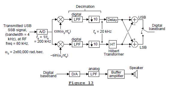
The Delay element in the upper path in Figure 13 is needed to maintain data synchronization with the time-delayed Hilbert transformer output sequence in the bottom path. For example, if a 21-tap digital Hilbert transformer is used, then the upper path’s Delay element would be a 10-stage delay line [2].
With DSP techniques enabling us to implement high performance, guaranteed linear-phase, Hilbert transformation, the phasing method of SSB demodulation has become popular in modern times.
LISTENING TO DONALD DUCK
You’ll notice that the phasing method of SSB demodulation assumes we have a BFO available in our receiver that’s identical in frequency and phase with the ωc oscillator in the SSB transmitter. If this not the case, then our demodulated baseband signals may have both frequency and phase errors. Those potential errors can be described as follows:
Let's assume an SSB transmitter baseband signal contains a single sinusoid of cos(ωmt + φ). If the demodulator’s local BFO, the cos() and -sin() oscillator combination, has a frequency error of Δω radians/second and a phase error of θ radians, then the SSB demodulated baseband sinusoids will be
USB demod sinusoid = cos[(ωm - Δω)t + φ - θ],
and an LSB mode demodulated baseband signal will be
LSB demod sinusoid = cos[(ωm + Δω)t + φ + θ].
The origin of those expressions is given in Appendix C.
If Δω = 0, a constant phase error of θ radians over the demodulated baseband signal’s full frequency range is not a problem in voice communications. The human ear/brain combination can tolerate audio phase errors, so we can correctly interpret such demodulated speech signals. I’m not a digital communications guy but I imagine that a few degrees of BFO phase error would render any sort of digital phase-modulated baseband signal useless in an SSB receiver.
When θ = 0, a BFO’s +Δω frequency error causes pitch shifting in that the demodulated baseband signal will be shifted in frequency. Figure 14(b) shows the situation where a BFO’s Δω frequency error causes the positive- and negative-frequency components of the baseband signal to overlap at zero Hz. In this situation a +Δω frequency error greater than roughly 75 Hz –to- 100 Hz renders the demodulated voice baseband unintelligible.
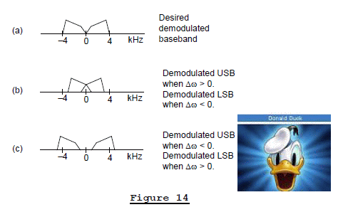
Figure 14(c) shows the demodulated baseband spectrum when a BFO’s -Δω frequency error causes the positive- and negative-frequency components of the baseband signal to be shifted away from zero Hz. This distorts the harmonic relation between baseband voice spectral components. In this scenario a -Δω frequency error greater than roughly 150 Hz –to- 200 Hz causes a demodulated voice baseband signal to sound like Donald Duck.
Intelligibility tests indicate that a Figure 14(c) BFO -Δω frequency error of less than, say, 150 Hz can be tolerated. The bottom line here is that using modern day high-precision frequency synthesis techniques, the Δω error of receiver BFOs can be kept small making SSB systems, with their narrow RF bandwidth requirement and transmission power efficiency, quite useful for voice communications over radio links.
CONCLUSION
So now we know how the synchronous detection and phasing methods of SSB demodulation work. We'll leave the "Weaver method" of SSB demodulation, itself a form of quadrature processing, as a topic for another blog. The "filtering method", as far as I can tell, doesn't seem to be used in modern digital implementations of SSB communications systems. If you'd like to review the mathematics of SSB systems, I recommend you check out the Internet references [3] and [4].
ACKNOWLEDGMENTS
I say “Thanks” to Tauno Voipio and Mark Goldberg for explaining so much SSB theory to me. You guys rock! Without your help this blog would not exist.

REFERENCES
[1] http://en.wikipedia.org/wiki/Single-sideband_modulation
[2] R. Lyons, “Understanding Digital Signal Processing”, 2nd & 3rd Editions, Prentice Hall Publishing, Chapter 9.
[3] http://local.eleceng.uct.ac.za/courses/EEE3086F/notes/508-AM_SSB_2up.pdf
[4] http://www.ece.umd.edu/~tretter/commlab/c6713slides/ch7.pdf
APPENDIX A – GENERATING SSB SIGNALS
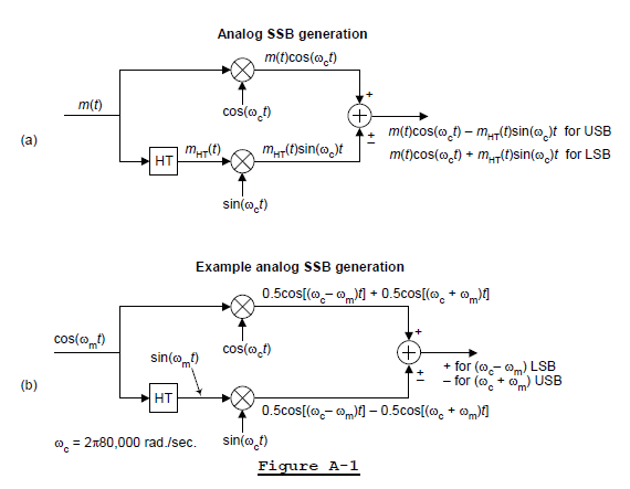
The phasing method of SSB generation is shown in Figure A-1(a), where m(t) is some generic baseband modulating signal. Some people call Figure A-1(a) a "Hartley modulator." A specific SSB generation example is given in Figure A-1(b). In that figure the baseband input is a single low-frequency analog cosine wave whose frequency is ωm radians/second. The output carrier frequency is ωc = 2π80000 radians/second (80 kHz).
A real-world example of a DSP version of this SSB generation method is shown in Figure A-2, where interpolation is needed so that multiplication by the high-frequency oscillator signals does not cause spectral wrap-around errors, as would happen if no interpolation was performed.
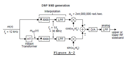
The baseband input sequence m(n) had a one-sided bandwidth of 3 kHz, and the final SSB output carrier frequency is 9 MHz. The interpolation by 3000 was performed by a cascade of three interpolation stages (interpolation factors 15, 25, and 8), with each stage using CIC lowpass filters. The output sample rate was chosen to be 36 MHz so that the oscillators' cos() and sin() sequences were [1,0,-1,0,...] and [0,1,0,-1,...], which eliminated the need for high-frequency multiplication.
APPENDIX B – THE HILBERT TRANSFORM AS A TRANSFER FUNCTION
In the time domain, the Hilbert transform (HT) of a real-valued cosine wave is a real-valued sinewave of the same frequency. And the HT of a real-valued sinewave is a real-valued negative cosine wave of the same frequency. Stated in different words, in the time domain the HT of a real-valued sinusoid is another real-valued sinusoid of the same frequency whose phase has been shifted by -90° relative to the original sinusoid. We validate these statements as follows:
If we treat the HT as a frequency-domain H(ω) transfer function, its |H(ω)| magnitude response is unity as shown in Figure B-1(b).

The phase response of H(ω) is that shown in Figure B-1(c), which we can describe using

where "arg" means the argument, or angle, of H(ω). This means that the HT of a real-valued cosine wave is

And the HT of a real-valued sinewave is

A detailed description of the HT and techniques for designing digital Hilbert transformers are given in reference [2].
I'll briefly mention that there are three reasonable ways to depict the HT in block diagrams. Those ways are shown in Figure B-2, where signal xH(t) represents the HT of input x(t) signal.

Although I understand why an author might use it, I don't particularly like the Figure B-2(a) notation. I prefer the notation in Figure B-2(b). By the way, I encountered the interesting Figure B-2(c) depiction of the HT on a web page produced by a professor at the University of Maryland. (It shows the professor's inclination to describe things in strictly mathematical terms.)
APPENDIX C – THE EFFECT OF LOCAL BFO FREQUENCY AND PHASE ERRORS
Using the phrase "BFO" to represent our phasing method demodulator's cos() and -sin() oscillators, Figure C-1 shows the USB-mode demodulated output baseband signal under the conditions:
- The transmitter's baseband signal is a single cos(ωmt + φ) sinusoid,
- The transmitted USB RF signal is a cos[(ωc + ωm)t + φ] sinusoid,
- The demodulator's BFO has a frequency error of Δω radians/second and a phase error of θ radians.

If Δω = 0 and θ = 0, then the demodulated output signal would be the original cos(ωmt + φ) baseband signal.
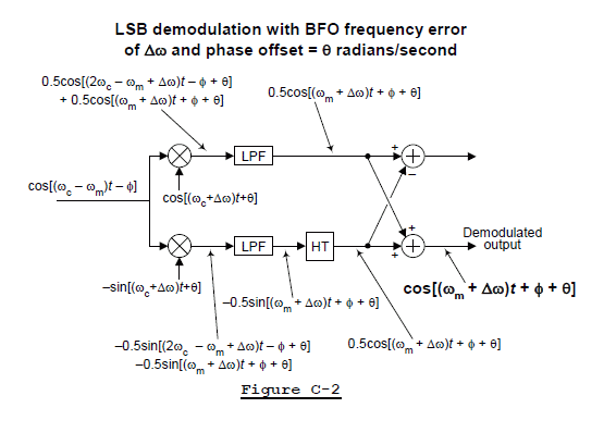
Figure C-2 gives a graphical derivation of a demodulated LSB-mode output signal when frequency and phase errors exist in the local BFO. Notice in the LSB-mode case, if an LSB transmitter's baseband signal contains a single sinusoid of cos(ωmt + φ), the transmitted RF LSB signal will be cos(ωmt - φ) having a negative initial phase angle.
- Comments
- Write a Comment Select to add a comment

Sorry, I don't understand your 1st question. Perhaps you could be more specific and tell me which paragraph, or figure, in my blog you're referring to when you ask that 1st question.
Your 2nd question is a super valid question. Here's the best answer I have:
Thinking about a complex signal that is A+jB, you cannot go to your local electronics store and buy a 'j-operator' component and solder it to a printed circuit board to form a complex signal. Implementing the j-operator is a conceptual "definition" that everyone agrees to.
For example:
Let's say you build a circuit that generates two real valued signals, Signal_1 and Signal_2. Then you bring everyone into the lab and say, "I am going to define a complex signal. That complex signal is Signal_1 + jSignal_2. Does everyone understand?" They all nod their heads in agreement. Then you continue with, "From now on, my Signal_1 is the real part (in-phase part, East-West part) of my complex signal and my Signal_2 is the imaginary part (quadrature phase part, North-South part) of my complex signal. Does everyone agree to this?" Everyone in the room nods their heads in agreement.
By having everyone agree to your definitions of what are the real and imaginary parts of your complex signal you have implemented the j-operator.
Another way to view your 2nd question is: Let's say real-valued Signal_1 and real-valued Signal_2 are analog sinewaves of the same frequency but with 90-degree phase between them. Apply Signal_2 to the vertical input of an oscilloscope and apply Signal_1 to the external horizontal input of the oscilloscope. By doing this, the screen of the oscilloscope becomes your complex plane and the scope's electron beam position on the screen is the instantaneous value of your complex signal Signal_1 + jSignal_2. If the frequency of the two sinusoids was 2 Hz, the electron beam will orbit two revolutions/second around in a circle on the oscilloscope's screen. So the act of connecting the two cables to the oscilloscope was in itself implementing the j-operator.
Hope that helps,
[-Rick-]

I can't understand why some comments here are totally against this great blog. I come from the old and the new school, demodulating SSB analogically but also with DSP. If someone does not understand the concepts of DSP it is not to attack this blog, they should first understand how things are done with DSP before saying that this blog is rubbish. You have done a great job here, my congratulations on that. And it has also shown that there are many people who, because they do not understand something, think that it is not valid. To those people I must tell them that all this theory that is here is very easily implemented in code. Because at the end of the day DSP is to do it by software.

Hello Deulis.
Thanks for your interesting and kind words. Take care.


Thanks for the thorough and well writing article. In appendix B you indicate a fifth reference. But in your reference list there are only four.


That '[5]' in Appendix B should be a '[2]'. I'll have that typo
corrected. Thanks for pointing that out to me.
[-Rick Lyons-]
Or write your own software to do this (but I recommend avoiding FFTs, as they are VERY VERY VERY difficult to write code to do), and use FIR Sinc filters in place of the FFT filters.
This is what I usually do for this kind of thing. I don't waste my time implementing Hilbert transforms and other nasty mathematical constructs for this arduous task of "quadrature", "complex", phase stuff. I just do the straight forward approach to removing unwanted nearby signals.

http://www.dsprelated.com/showarticle/192.php
All AM signals require mixing the sideband(s) down to audio.
With "AM", ie carrier with two sidebands, the carrier of the transmitted signal mixes with the sidebands on the receiver's detector to get back to "baseband".
With SSB, ie a single sideband with no carrier, the "carrier" has to be inserted at the receiver end, so the sideband can be mixed down to "baseband". With SSB, there is nothing to synchronize the reinserted carrier with the missing carrier.
Thus "synchronous detection" doesn't work with SSB. If the reinserted carrier is not in the right place, the result is odd sounding "baseband".
The only way to get "perfectly" tuned SSB is to either keep to very absolute frequencies, in both transmitter and receiver, or send the carrier from the transmitter (which wastes transmitter power, and causes heterodynes)
If you send both sidebands, the reinserted carrier at the receiver can be set just right because the two sidebands provide enough information. That's synchronized detection.
If both sidebands are sent, you cannot place the carrier properly unless you synchronize the reinserted carrier to the incoming signal. Mistuning the reinserted carrier means not only that the audio tones at "baseband" are in the wrong place, but each sideband (which are mirror images of each other) land in the wrong place at baseband so it's all comprehensible. A 1KHz tone at the transmitter should be at 1KHz at the receiver, but if the reinserted carrier at the receiver is mistuned, say by one Hertz, one sideband would convert to 1001KHz at baseband, and the other sideband to 999KHz.
One common trick is to convert the DSB signal to SSB at the receiver, using an SSB filter, so the receiver only sees an SSB signal. Though, sending both sidebands can be of value, if demodulated properly, the redundant sideband can improve reception (despite the cost of the wider bandwidth and the power used at the transmitter to send that extra sideband.
If the carrier is sent along with the sidebands, the reinserted carrier can be placed properly, either by syncing to the carrier from the transmitter, or from the two sidebands. There is use to this, if the carrier fades.
The filter method, the phasing method and the Weaver method are not about getting the signal back to baseband, but methods eliminating the unwanted sideband. Note that in the case of an SSB signal from the transmitter, it's about knocking out the interfering signal the other side of zero beat.
Mixing causes sidebands or images, whether in a superheterodyne or balanced modulator in an SSB transmitter, or getting signal back down to baseband. The terminology changes, even if it really is the same thing. You can use filters or the phasing method to get rid of the image in a receiver, or use the same thing to get rid of the unwanted sideband.
Michael

This is the first time I've managed to find an explanation that makes some sense on the internet. That said I'm new to this so I'm going to ask what is probably a dumb question but.... For the BFO would there be some kind of feedback mechanism in a normal receiver to try and eliminate the "Donald Duck" effect by tweaking the oscillator frequency?

Hello anrstone,
Please forgive me, for I'm not able to answer your very sensible question. Perhaps information from ARRL people who actually build DSP radios will be of some help to you. That information can be found at the following two web sites:
http://www.arrl.org/dsp-digital-signal-processing
http://www.arrl.org/software-defined-radio#dsp10
Good Luck.
Great thanks - I have read your article a few times and I have a project in mind to decode a NAVTEX signal so I think I'm going to give up the theory and get stuck in with the practical to some extent!
The feedback mechanism is as follows: If the voices sound DonaldDucky, then adjust the tuning knob. No automatic method possible in the general case. For example, a 1khz tone into the mike of a USB transmitter with a suppressed carrier at 1mhz sends out what appears to be a clean carrier at 1.001mhz, there is no way for the receiver to know at what audio frequency the tone into the transmitter's mike was. These days with accurate and agile local oscillators (for use below 100mhz the $1 Si5351 is sufficient), we can solve the problem by agreeing to restrict the suppressed carrier to specific frequencies, perhaps integer multiples of 5khz.
Thank you for the article, with 'just enough' math.
Question about 'phasing' or 'quadrature' method of SSB demodulation. On Figures 10, 11 we get quadrature baseband signals i(t) and q(t), for subsequent Hilbert transform. Apparently, Hilbert transform can be done by IIR filter, for example following Theodor A. Prosch, "A Minimalist Approximation of the Hilbert Transform", Sept/Oct 2012 QEX, pp 25-31. Unfortunately, using a pair of IIR all-pass filters for each signals i(t) and q(t), we split each of them in two, so total will be four signals.
Is any way to apply IIR all-pass filters 'in reverse': so they take two quadrature signals i(t) q(t) as input, and produce only one output signal - USB or LSB? Looking into simple digital implementation of IIR filter, someone can reverse it.
Before doing that, I wonder what DSP theory thinks about it (I'm reading the "Understanding Digital Signal Processing")
Thank you
Konstantin VA7FFT

Hello Konstantin.
I was not able to find a copy of the Theodor A. Prosch article on the Internet, so I have no idea what is his method of performing a Hilbert transform. Is it possible for you to provide a copy of Prosch's article to me?
Konstantin, if you have a copy of my "Understanding DSP" textbook then you may want to visit the following web page:
https://www.dsprelated.com/showarticle/1094.php
Rick,
your illustration of Quadrature Processing starts from the assumption that User1 signal is sine wave, and User2 signal is cosine wave. Because of that they have different baseband Real and Imag charts, which helps to demodulate them in Figure 12. What if User1 signal is also cosine wave, similar to User2, how charts change? It should be irrelevant! The only criteria for User1 and User2 should be the use of Upper and Lower SideBands, to distinguish them at the end. Where is that pivot point? I tried to redraw charts when User1 signal is cosine wave - it's not distinguishable from User2.
Thank you!
Konstantin VA7FFT


Hello Rick
Could you please show the Real and Imag charts right after downconversion i(t) q(t) and before and after Hilbert transformer? Where is the phase rotating differently for USB and LSB?
I agree with the resulting charts on the right, my quadrature radio works this way.
Thank you
Konstantin VA7FFT

Hi Konstantin. To you I have e-mailed the figures you requested regarding my above 1/23/2019 reply. Below are the figures but I don't know if the following will be "readable" here, or not.

I believe you can also perform the audio recovery by multiplying the baseband SSB signal by a cosine function that has the frequency of the upper audio bandwidth. This would recover the "other side" of the audio spectrum. You could multiply by the cosine of the upper audio frequency again, and shift the recovered audio spectrum back down to baseband. Then just lowpass filter the higher frequency copies of the sideband, keeping only the recovered audio signal. You could even combine the two cosine multiplications into one operation. I believe this operation should work for either USB or LSB.
1. Multiply baseband SSB signal by cosine^2 of the upper audio frequency.
2. Lowpass filter with a cutoff of slightly less than the upper audio frequency.
When I have some free time (Ha!) I might try writing an octave script to test this out.

Hi Jess_Stuart. You wrote, "I believe you can also perform the
audio recovery by multiplying the baseband SSB signal by a cosine
function that has the frequency of the upper audio bandwidth."
I'm not sure what you phrase "baseband SSB signal" means. Is the "baseband SSB signal" you're referring to shown in any figure of my blog?
Hello Rick - I came across this article by accident as I was looking for some pre-written article on the phasing method of SSB demodulation to explain to a wider audience how the cave radio I was working on worked. Then to my surprise (and wonder!) I see that the example shown here is to work at a very similar target frequency of 80kHz (in my case 87kHz to be compatible with previous analogue systems). I also did a double take as you spoke of a sample frequency of the ADC of 200kHz - which is what I use to be able to get up to 87kHz on the Sigma delta convertor from Cirrus ( cs5340). I wonder what your application was in the system described? Anyway my project is still a work in progress, but have at least a working prototype of a transceiver using a Cora Z7 board and a simple add on board. The demodulator is however slightly different as the two paths use FIRs to give +45 and -45 degree shifts rather than the typical delay and Hilbert to get a 90 degree relative phase out. This is suggested by the FIR design site at Iowa Hills (http://iowahills.com/). The modulator doesn't use phasing or weaver but a slightly different (and hopefully you might think novel) method: phase the audio plus and minus 45 degree, send to a Cordic to determine instantaneous phase and then frequency from the deltas - add to a fixed frequency and use to synthesize a PWM signal. The amplitude from the Cordic is used to determine the pulse width and then the PWM can be used to drive a more efficient class D output stage. Anyway work in progress as I say (code at https://github.com/AssociationNicola/N4Z-FPGA-code... ). The audio is routed in and out through a python script and to a bluetooth headset to make a cost-effective radio for use in caves (rescue and the likes). Anyway - nice article, thanks.

Hello Nibbs. Thanks for your interesting comment.
I'm going to check out the Iowa Hills web page. Good luck with your cave radio!
To post reply to a comment, click on the 'reply' button attached to each comment. To post a new comment (not a reply to a comment) check out the 'Write a Comment' tab at the top of the comments.
Please login (on the right) if you already have an account on this platform.
Otherwise, please use this form to register (free) an join one of the largest online community for Electrical/Embedded/DSP/FPGA/ML engineers:


