


Reducing IIR Filter Computational Workload
This blog describes a straightforward method to significantly reduce the number of necessary multiplies per input sample of traditional IIR lowpass and highpass digital filters.
Reducing IIR Filter Computations Using Dual-Path Allpass Filters
We can improve the computational speed of a lowpass or highpass IIR filter by converting that filter into a dual-path filter consisting of allpass filters as shown in Figure 1.
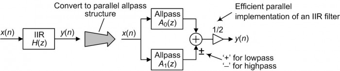
FIGURE 1. IIR filter –to– dual-path allpass filters conversion.
The dual A0(z) and A1(z) filter paths in Figure 1 are cascades of simple 1st- and 2nd-order allpass filters. (Allpass filters are a specialized class of IIR filters whose frequency magnitude responses are constant over the full frequency range from zero to the fs input data sample rate [1].)
Figure 2 shows an example of this standard IIR –to– parallel allpass filter conversion process, where our original IIR filter is a 5th-order lowpass filter.
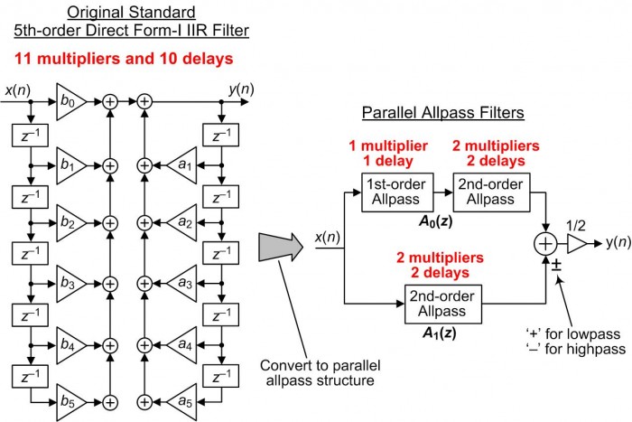
FIGURE 2. Example of "standard" IIR filter –to– parallel-path allpass filter conversion.
The original IIR and the dual-path filters in Figure 2 have identical frequency magnitude responses. A key point of this blog is that the filter on the left side of Figure 2 requires 11 multiplies per input sample whereas the parallel filter on the right side only requires five multiplies per input sample.
Details of the allpass sections within the 5th-order dual-path filter on the right side of Figure 2 are given in Figure 3. The ck coefficients are real-valued scalars.
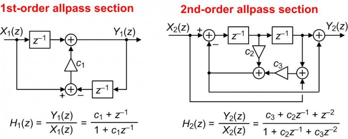
FIGURE 3. 1st- and 2nd-order allpass sections and their z-domain transfer functions.
We see in Figure 3 that H1(z) and H2(z) are indeed allpass filters because their numerator coefficients are in reverse order from their denominator coefficients.
At first glance the notion of implementing a lowpass or highpass IIR filter using allpass filters seems impossible. An explanation of how this is possible is found in Reference [2], graciously supplied online by its author DSP guru fred harris.
As additional examples, we show the result of our standard IIR –to– dual-path allpass conversion for standard 3rd-, 7th-, and 9th-order IIR filters in Figure 4.
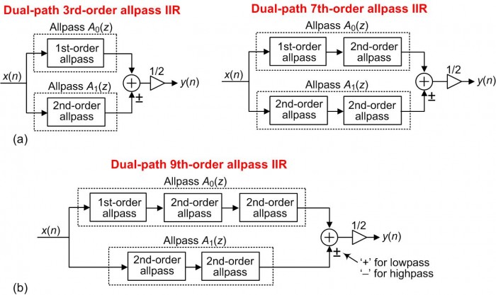
FIGURE 4. Dual-path allpass IIR filters: (a) 3rd- and 7th-order; (b) 9th-order.
Computational Savings When Using the Dual-Path Allpass Filters
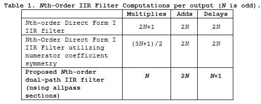
Table 1 compares the computational workloads of traditional Direct Form I IIR filters relative to the dual-path IIR filters in Figures 3 and 4. The bottom row of Table 1 illustrates the computational advantage of the dual-path allpass filters.
To keep this blog from being too lengthy, the PDF file associated with this blog provides:

References
[1] S. Mitra, Digital filter lecture slides (allpass filter discussion starts at slide# 23).
Available at:http://www.emba.uvm.edu/~gmirchan/classes/EE275/Handouts_Ed4/Ch07(4e)Handouts/Ch7(1)Handouts_4e.pdf
[2] f. harris, "A Most Efficient Digital Filter: The Two-Path Recursive All-Pass Filter", Streamlining Digital Signal Processing, A Tricks of the Trade Guidebook (IEEE Press/Wiley, 2007), Chapter 9, pp. 85-104. Available at:
https://www.researchgate.net/publication/278320928_A_Most_Efficient_Digital_Filter_The_Two-Path_Recursive_All-Pass_Filter

- Comments
- Write a Comment Select to add a comment
Hi Rick,
There is another aspect of the filters that I find more important when it comes to saving computations for the all-pass composition. Because perhaps in practice a special realization for the allpass filters are not so convenient. At least not for fixed-point where DF1 is preferred. But you can get one filter almost for free if you do a band-split. So if you realize a 3rd order Butterworth LP filter you can obtain the 'complementary' HP filtered output by just one arithmetic operation (almost free). This is due to the power-complementary property of the allpass decomposition. However, the composition only works for odd-ordered LP/HP filters in contrast to the Linkwitz-Riley which only works for even-ordered. Great article and a nice reference.

Hi niarn. Yes, you're right! I saw those complementary filters in the Mitra and Vaidyanathan books. But I didn't seen any suitable application for those complementary filters.
My impression is that they are used in audio and music DSP. For instance in compressors and limiters. Basically anywhere you want to divide an input into bands (similar to FFT) and apply a gain to those bands. Then the power-complementary property ensures that when the bands are summed up then you get a very nice magnitude response which corresponds to the gains applied for the bands. There is of course phase distortion corresponding to allpass filtering. But phase is not always that important in audio and music. Perhaps one could say that anywhere you want to have a filter with a dynamic magnitude response (and don't care much about phase) could potentially use allpass decomposition.

Is there a variation on these half-bands for decimation by two? Another topology that gives a similar by-2 poly-phase processing gain that you get from FIR half-band filters?
Thanks in advance,
Mark Napier
Hi Mark. Perhaps the material in my above Reference [2] (click on the red-font link) will answer your question.
To post reply to a comment, click on the 'reply' button attached to each comment. To post a new comment (not a reply to a comment) check out the 'Write a Comment' tab at the top of the comments.
Please login (on the right) if you already have an account on this platform.
Otherwise, please use this form to register (free) an join one of the largest online community for Electrical/Embedded/DSP/FPGA/ML engineers:


