


60-Hz Noise and Baseline Drift Reduction in ECG Signal Processing
Electrocardiogram (ECG) signals are obtained by monitoring the electrical activity of the human heart for medical diagnostic purposes [1]. This blog describes a very efficient digital filter used to reduce both 60 Hz AC power line noise and unwanted signal baseline drift that often contaminate ECG signals.
We'll first describe the ECG noise reduction filter and then examine the filter's performance in a real-world ECG signal filtering example.
Proposed ECG Noise Reduction Digital Filter
To reduce unwanted ECG signal baseline drift and 60 Hz powerline noise contamination we want a linear-phase wideband digital filter with notches at zero Hz and 60 Hz. We obtain such a filter by first modifying the linear-phase unity-gain DC removal filter proposed in [2]. That DC removal filter is shown in Figure 1(a).
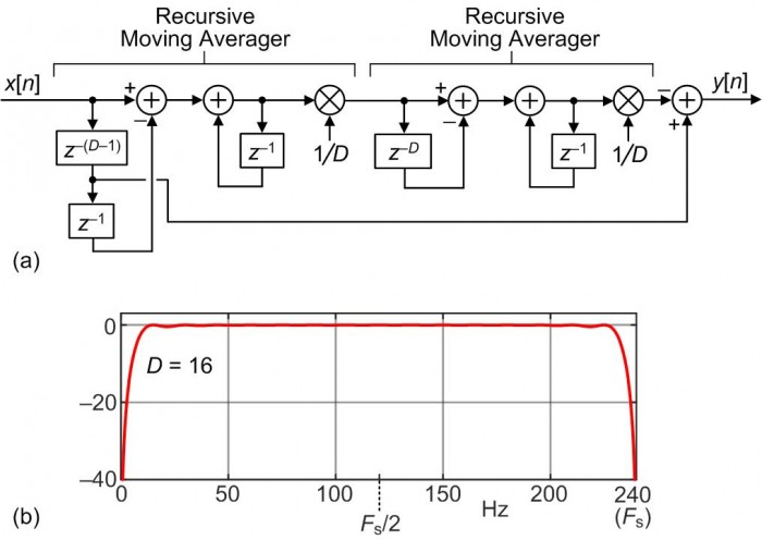
FIGURE 1. DC removal filter: (a) filter structure, (b) frequency
magnitude response when D = 16 and Fs = 240 Hz.
The details of the DC removal filter's characteristics are given in [2], however what interests us here is the filter's frequency magnitude response given in Figure 1(b) for D = 16 and a data sample rate of Fs = 240 Hz. As derived in Appendix A, the DC removal filter's z-domain transfer function is:
$$H_{\tt DC-Rem}(z) = {-1/D^2+z^{-(D-1)}+(2/D^2-2)z^{-D}+z^{-(D+1)}-(1/D^2)z^{-2D}\over 1-2z^{-1}+z^{-2}}.\qquad(1)$$
The DC removal filter can be modeled with the following MATLAB code:
Fs = 240; D = 16;
B = [-1/D^2, zeros(1,D-2), 1, (2/D^2-2), 1, zeros(1,D-2), -1/D^2];
A = [1, -2, 1];
freqz(B, A, 1024, 'whole', Fs);
To produce the transfer function of our desired ECG filter we replace each z‑1 in Eq. (1) with z‑4 as:
$$H_{\tt ECG}(z) = {-1/D^2+z^{-4(D-1)}+(2/D^2-2)z^{-4D}+z^{-4(D+1)}-(1/D^2)z^{-8D}\over 1-2z^{-4}+z^{-8}}.\qquad(2)$$
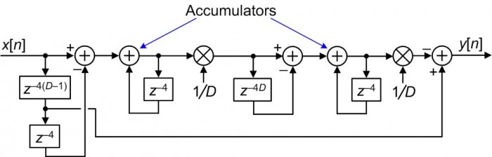
The desired ECG filter corresponding to Eq. (2) is shown in Figure 2(a).
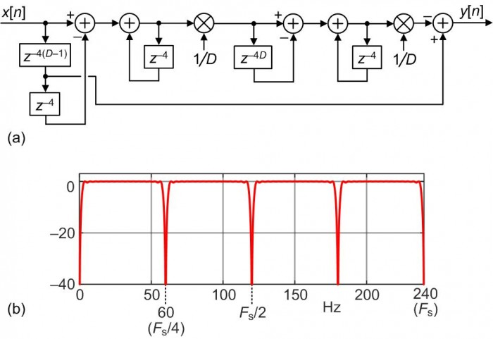
FIGURE 2. Proposed ECG signal drift and 60 Hz noise reduction
filter: (a) filter structure, (b) frequency magnitude
response when D = 16 and Fs = 240 Hz.
The frequency magnitude response of the Figure 2(a) filter, for D = 16 and Fs = 240 Hz, is shown in Figure 2(b). (That magnitude response is the Figure 1(b) magnitude response compressed by a factor of four.) In Figure 2(b) we see the desired filter notch at zero Hz for attenuating low-frequency signal baseline drift and a notch at 60 Hz to attenuate AC power line noise.
Several practical implementation issues regarding the proposed Figure 2(a) ECG filter are presented in Appendix B, and that filter can be modeled with the following MATLAB code:
Fs = 240; D = 16;
B = [-1/D^2, zeros(1,4*D-5), 1, 0, 0, 0, (2/D^2-2), 0, 0, 0, 1, zeros(1,4*D-5), -1/D^2];
A = [1, 0, 0, 0, -2, 0, 0, 0, 1];
freqz(B, A, 1024, 'whole', Fs);
ECG Filter Computational Efficiency
To appreciate its high computational efficiency, note that the proposed ECG filter requires two multiplications and five additions per input sample. A linear-phase Parks-McClellan designed FIR filter with a frequency magnitude response similar to Figure 2(b), using a "folded" delay line structure, requires 122 multiplications and 224 additions per input sample.
An Example of ECG Noise Reduction
Figure 3(a) shows an actual ECG signal I downloaded from [3] and resampled to a sample rate of Fs = 240 Hz. Figure 3(b) shows the ECG signal after I contaminated the original ECG signal with a slow baseline drift (what we'd call a "fluctuating DC bias") having a peak to peak amplitude of one.
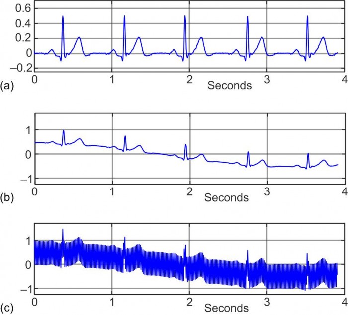
FIGURE 3. Real-world ECG signal: (a) original noise-free
signal; (b) original noise-free ECG signal contaminated
with baseline drift; (c) original noise-free ECG signal
contaminated with baseline drift and 60 Hz noise.
Figure 3(c) shows the Figure 3(b) ECG signal further contaminated with significant 60 Hz noise. The signal to noise ratio of the noisy Figure 3(c) signal is roughly -25 dB.
When we apply the noisy Figure 3(c) signal to our proposed ECG filter, with D = 16, the filter's output is shown in Figure 4. We see in Figure 4 that after the filter's transient response we have recovered the original Figure 3(a) ECG signal.
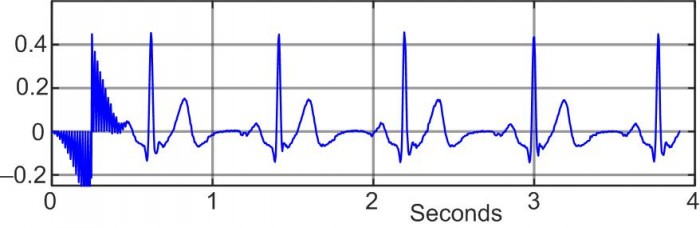
FIGURE 4. Proposed ECG filter output signal when its input
is the noisy Figure 3(c) signal and D = 16.
Conclusions
I proposed the very efficient Figure 2 unity-gain linear-phase filter that reduces both unwanted signal baseline drift and 60 Hz powerline noise in ECG signals. In addition I listed several important filter implementation topics in Appendix B. Finally I showed the proposed ECG filter in action in an example of reducing baseline drift and 60 Hz noise contaminating a real world ECG signal.

References
[1] Kher, R., "Signal Processing Techniques for Removing Noise from ECG Signals", Biomedical Engineering and Research, Vol. 3, No. 101, March 2019. http://www.jscholaronline.org/articles/JBER/Signal-Processing.pdf#:~:text=The%20ECG%20signal%20is%20generated%20by%20contraction%20%28depolarization%29,and%20a%20T%20wave%20%28due%20to%20ventricular%20repolarization%29.
[2] Lyons, R., "Linear-phase DC Removal Filter", dsprelated.com, March 2008, (See Figure 2.) https://www.dsprelated.com/showarticle/58.php[3] Shimmer Research, https://www.shimmersensing.com/support/sample-data...
Appendix A: Derivation of Eq. (1)
$$H_{\tt RMA}(z) = {1\over D}·{1-z^{-D}\over 1-z^{-1}}.\qquad\qquad\qquad\qquad\qquad\qquad\qquad(\tt A-1)$$
Next, the transfer function of two cascaded recursive moving averagers is:
$$H_{\tt Dual-RMA}(z) = \left [{1\over D}·{1-z^{-D}\over 1-z^{-1}}\right]^2.\qquad\qquad\qquad\qquad\qquad\qquad(\tt A-2)$$
The transfer function of the Figure 1(a) DC removal filter is then:
$$H_{\tt DC-Rem}(z) = z^{-(D-1)}-\left [{1\over D}·{1-z^{-D}\over 1-z^{-1}}\right]^2.\qquad\qquad\qquad\qquad\qquad(\tt A-3)$$
To convert Eq. (A-3) to a ratio of polynomials we square its bracketed term yielding:
$$H_{\tt DC-Rem}(z) = z^{-(D-1)}-{1\over D^2}·{1-2z^{-D}+z^{-2D}\over 1-2z^{-1}+z^{-2}}$$
$$= z^{-(D-1)}-{1/D^2-(2/D^2)z^{-D}+(1/D^2)z^{-2D}\over 1-2z^{-1}+z^{-2}}.\qquad\qquad\qquad(\tt A-4)$$
Finally, putting both terms of Eq. (A-4) over a common denominator we have our desired transfer function:
$$H_{\tt DC-Rem}(z) = {z^{-(D-1)}(1-2z^{-1}+z^{-2})-1/D^2+(2/D^2)z^{-D}-(1/D^2)z^{-2D}\over 1-2z^{-1}+z^{-2}}$$
$$= {-1/D^2+z^{-(D-1)}+(2/D^2-2)z^{-D}+z^{-(D+1)}-(1/D^2)z^{-2D}\over 1-2z^{-1}+z^{-2}}.\qquad(\tt A-5)$$
Appendix B: ECG Filter Implementation Issues
Issue# 1:The proposed ECG filter is based on the assumption that the input signal sample rate is Fs = 240 Hz. If you're processing a previously-collected ECG signal whose sample rate is not 240 Hz then resampling your ECG signal to a sample rate of 240 Hz will be necessary. In geographical locations that use 50 Hz AC power the sample rate of the digitized ECG signal must be Fs = 200 Hz.
Issue# 2:
Figure 2(a)'s delay variable D controls the width of the ECG filter's notches. The larger is D the more narrow are the notches as shown in Figure B-1.
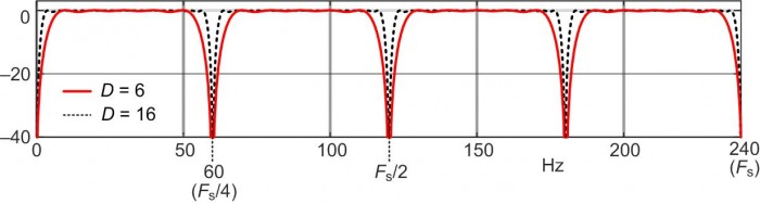
D = 6 (solid curve) and D = 16 (dashed curve).
Issue# 3:
If you're able to use a value for the delay variable D that is an integer power of two then the ECG filter's two multiplications by 1/D can be implemented by simple binary right-shift operations.
Issue# 4:
The ECG filter in Figure 2(a) contains two accumulators (integrators), shown in Figure B-2, that can experience data over
Using two's complement fixed-point arithmetic avoids accumulator overflow errors if we ensure that an accumulator's bit width is at least:
$${\tt accumulator}\hspace{5 pt}{\tt bits} = {\tt number}\hspace{5 pt}{\tt of}\hspace{1 pt}\hspace{5 pt}{\tt bits}\hspace{5 pt}{\tt in}\hspace{5 pt} q[n] + \lceil log_2(D)\rceil$$
where q[n] is the forward input sequence to an accumulator, and $\lceil{k}\rceil$ means: if k is not an integer, round it up to the next larger integer.
Issue# 5:
When the ECG filter is implemented using floating-point arithmetic no accumulator overflow errors will occur. In that case we can eliminate one of the filter's multipliers and use the filter shown in Figure B-3.
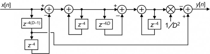
The Figure B-3 filter's transfer function is Eq. (2).
Issue# 6:
This last implementation issue involves the amplitudes of the P, R, and T waves within an ECG rhythm as shown in Figure B-4.
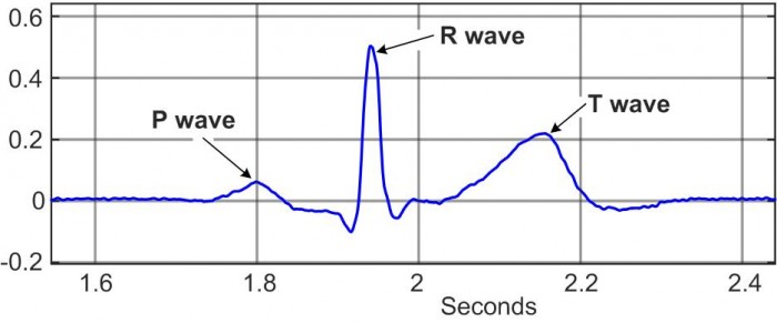
Regardless of the value used for the delay variable D, the proposed Figure 2 ECG noise reduction filter will remove unwanted baseline drift and 60 Hz noise. However, a small value for D will result in a wide filter notch at zero Hz. Because the P and T waves in Figure B-4 contain more lower frequency content than the narrow impulsive R wave, a small value for D will attenuate the P and T waves' amplitudes more than the R wave's amplitude. We don't want that to happen.
According to my testing, as limited as it may be, to avoid excessive attenuation of the P and T waves I recommend a D value of D ≥ 16.


- Comments
- Write a Comment Select to add a comment

Thanks Rick, useful and interesting area of design. It is also critical. Imagine the design resulted in false deep Q wave that will mislead the poor graduate doctor to diagnose an old infarction. By the way the Q waves in your diagram look a bit deep?
A great idea, Rick!
Here's the filter's performance for D=24, on an ECG tainted with 50Hz powerline interference (output adjusted to account for the filter's group delay):
It works pretty well, and the implementation is so light, so this will be good for Cortex-M0 devices - we'll play with it a little more.
with kind regards,
Sanjeev.

Hi Sanjeev.
Thanks for the aligned input/output signal plots in your RLFilter.png file!
Hi,
Can you send the example code at this?
Thanks.
Hello Rick,
I found this article very useful. Thank for this article.
I have a basic question,
We have major ECG frequency spectrum till ~35Hz, so why we need 60Hz notch?
We can use a high order LPF below 50/60 Hz.
Hello rahulsb20.
I agree that most of the spectral energy of a noiseless ECG signal is below, say, 40 Hz. And yes, you could use a lowpass filter whose cutoff frequency is just below 50 or 60 Hz. But such a filter has two disadvantages; (1) it would not reduce any fluctuating DC bias noise (low frequency signal drift noise) that may be contaminating the ECG signal, and (2) it would require more arithmetic computations per output sample than my proposed Figure 2 ECG noise reduction filter.
To post reply to a comment, click on the 'reply' button attached to each comment. To post a new comment (not a reply to a comment) check out the 'Write a Comment' tab at the top of the comments.
Please login (on the right) if you already have an account on this platform.
Otherwise, please use this form to register (free) an join one of the largest online community for Electrical/Embedded/DSP/FPGA/ML engineers:


