


Phase Delay
The phase response
![]() of an LTI filter gives the radian
phase shift added to the phase of each sinusoidal component of the
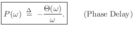
input signal. It is often more intuitive to consider instead the
phase delay, defined as
of an LTI filter gives the radian
phase shift added to the phase of each sinusoidal component of the
input signal. It is often more intuitive to consider instead the
phase delay, defined as
From a sinewave-analysis point of view, if the input to a filter with
frequency response
![]() is
is
![\begin{eqnarray*}
y(n) &=& G(\omega) \cos[\omega nT + \Theta(\omega)]\\
&=& G(\omega) \cos\{\omega[nT - P(\omega)]\}
\end{eqnarray*}](http://www.dsprelated.com/josimages_new/filters/img889.png)
and it can be clearly seen in this form that the phase delay expresses the phase response as a time delay in seconds.
Next Section:
Phase Unwrapping
Previous Section:
Example LPF Frequency Response Using freqz


