


Phase and Amplitude Calculation for a Pure Complex Tone in a DFT using Multiple Bins
Introduction
This is an article to hopefully give a better understanding of the Discrete Fourier Transform (DFT) by deriving exact formulas to calculate the phase and amplitude of a pure complex tone from several DFT bin values and knowing the frequency. This article is functionally an extension of my prior article "Phase and Amplitude Calculation for a Pure Complex Tone in a DFT"[1] which used only one bin for a complex tone, but it is actually much more similar to my approach for real valued tones in my article "Phase and Amplitude Calculation for a Pure Real Tone in a DFT: Method 1"[2].
The Base Definitions
The same variables and equation for describing the tone from my previous articles will be used. The variables are amplitude ($ M $), frequency ($ f $), phase ($ \phi $), and the sample count in the frame ($ N $). The signal definition is: $$ S_n = M \cdot { e^{ i(\alpha n + \phi) } } \tag {1} $$ Where: $$ \alpha = f \cdot \frac{ 2\pi }{ N } \tag {2} $$ The same $1/N$ normalized DFT definition is also used. $N$ is also the number of bins in the DFT so $k$ ranges from $0$ to $N-1$. $$ Z_k = \frac{ 1 }{ N } \sum_{n=0}^{N-1} { S_n e^{ -i\beta_k n } } \tag {3} $$ Where: $$ \beta_k = k \cdot \frac{ 2\pi }{ N } \tag {4} $$
Finding the Frequency
If the frequency of the tone is not known, the two or three DFT bin values nearest the peak magnitude bin can be used to find it. If the magnitude of a bin adjacent to the peak is fairly large, the two bin frequency calculation formula should be used[3]. If the bins adjacent to the peak are small in comparison, the three bin formula [4] centered at the peak should be used. In either case, the frequency can be calculated. In the noiseless single tone case, the calculation will be exact. There are other estimation methods as well.
Integer Frequency Case
If the frequency is an integer value in terms of cycles per frame, the next few sections do not apply. Simply set $q$ to the bin value of the frequency bin and skip ahead to the "Final Results" section.
Bin Value Formula for a Pure Complex Tone
The alternative bin value formula found in my previous blog article titled "DFT Bin Value Formulas for Pure Complex Tones" [5] will be used instead of the main one. The reason is that it replaces a complex valued divide with a real valued one. This saves a lot of calculations.
First a change of variable is needed [Edit 2022-09-23, thanks echo21]: $$ \delta_k = \beta_k - \alpha \tag {5} $$ The formula is then: $$ Z_k = \frac{ M }{ N } e^{ i \left[ -\delta_k (N-1) / 2 + \phi \right] } \cdot \frac{ \sin( \delta_k N / 2 ) }{ \sin( \delta_k / 2 ) } \tag {6} $$
Vector Formulation
The formula (6) can be rearranged slightly to make it more stackable. $$ Z_k = q \cdot e^{ i \left[ -\delta_k \frac{(N-1)}{2} \right] } \cdot \frac{ \sin( N \delta_k / 2 ) }{ N \sin( \delta_k / 2 ) } \tag {7} $$ Where: $$ q = M e^{ i \phi } \tag {8} $$ The complex value $q$ contains the amplitude and phase being sought. Therefore this is the value to be solved for. This can be done by stacking the bin value equations around the peak bin $p$ into a vector equation. The size of the vectors is flexible. $$ \begin{bmatrix} . \\ . \\ Z_{p-1}\\ Z_{p}\\ Z_{p+1}\\ . \\ . \\ \end{bmatrix} = q \cdot \begin{bmatrix} . \\ . \\ e^{ i \left[ -\delta_{p-1} \frac{(N-1)}{2} \right] } \cdot \frac{ \sin( N \delta_{p-1} / 2 ) }{ N \sin( \delta_{p-1} / 2 ) } \\ e^{ i \left[ -\delta_{p} \frac{(N-1)}{2} \right] } \cdot \frac{ \sin( N \delta_{p} / 2 ) }{ N \sin( \delta_{p} / 2 ) } \\ e^{ i \left[ -\delta_{p+1} \frac{(N-1)}{2} \right] } \cdot \frac{ \sin( N \delta_{p+1} / 2 ) }{ N \sin( \delta_{p+1} / 2 ) } \\ . \\ . \\ \end{bmatrix} \tag {9} $$ This equation is much simpler in vector notation. $$ \vec Z = q \vec Y \tag {10} $$ $\vec Z$ has the selected bin values from the DFT and $\vec Y$ is the calculated basis vector.
Solving for q
Finding $q$ is a standard Linear Algebra best fit with a single basis vector. Dotting both sides of (10) with the complex conjugate of $\vec Y$ turns the vector equation into a simple scalar one. $$ \vec Z \cdot \vec Y^* = q \vec Y \cdot \vec Y^* \tag {11} $$ The value of $q$ can now be calculated. $$ q = \frac{ \vec Z \cdot \vec Y^* }{ \vec Y \cdot \vec Y^* } \tag {12} $$
The Final Results
Thanks to the polar form of complex numbers, once the value of q is known finding the values of $\phi$ and $M$ is very straightforward. $$ \phi = \arg( q ) = \operatorname{atan2}( Im[q], Re[q] ) \tag {13} $$ $$ M = \| q \| = \sqrt{ (Im[q])^2 + (Re[q])^2 } \tag {14} $$ That's all there is to it.
Numerical Results
Here are some numeric results for using different length vectors. A length one vector is identical to the one bin solution provided in my previous blog article[1]. The result values are the RMS values for the errors multiplied by 100. The magnitude of the signal is one.
***********************************************************

The sample count is 32
and the run size is 10000
 The phase value is  0.123400

Errors are shown as RMS at 100x actual value

Target Noise Level = 0.100

Freq   One Vec     Two Vec    Three Vec   Four Vec    Five Vec
      Phase Mag   Phase Mag   Phase Mag   Phase Mag   Phase Mag
---- ------------ ----------- ----------- ----------- -----------
3.1   1.30 1.27   1.28 1.27   1.28 1.26   1.28 1.26   1.28 1.26
3.2   1.35 1.36   1.31 1.33   1.29 1.31   1.29 1.30   1.28 1.30
3.3   1.49 1.49   1.36 1.37   1.33 1.34   1.31 1.33   1.30 1.32
3.4   1.68 1.68   1.39 1.41   1.35 1.37   1.32 1.34   1.31 1.33
3.5   1.96 1.98   1.40 1.41   1.36 1.37   1.33 1.33   1.31 1.32
3.6   1.69 1.68   1.40 1.40   1.37 1.37   1.34 1.33   1.33 1.32
3.7   1.48 1.47   1.36 1.35   1.33 1.32   1.31 1.31   1.30 1.30
3.8   1.38 1.36   1.33 1.32   1.32 1.30   1.31 1.29   1.31 1.29
3.9   1.30 1.30   1.30 1.29   1.29 1.29   1.29 1.28   1.29 1.28

***********************************************************
The results clearly show that when a frequency is near an integer bin, increasing the number of bins in the vector does not significantly improve the results. However, when the frequency is closer to being between two bins, having more leakage, using the extra bin values reduces the errors. The values in the last two columns indicates diminishing returns on extra bins.
Conclusion
The phase and amplitude calculations of a pure complex tone from DFT bin values are significantly simpler than for a real valued tone. The derivation presented in this article is not very complicated and the results are easy to verify. It is important to keep in mind that these equations are exact as no approximation were used in their derivation.
References
[1] Dawg, Cedron, Phase and Amplitude Calculation for a Pure Complex Tone in a DFT
[2] Dawg, Cedron, Phase and Amplitude Calculation for a Pure Real Tone in a DFT: Method 1
[3] Dawg, Cedron, A Two Bin Exact Frequency Formula for a Pure Complex Tone in a DFT
[4] Dawg, Cedron, Three Bin Exact Frequency Formulas for a Pure Complex Tone in a DFT
[5] Dawg, Cedron, DFT Bin Value Formulas for Pure Complex Tones


- Comments
- Write a Comment Select to add a comment
Thread about sign errors
Hi Cedron,
thanks for providing the community with your solutions!
A colleague of me and I independently implemented Matlab code from your formulae (1) (the signal Sn) and (13) (the estimated phase).
We get Z_k for formula (12) from
(20) Z_k = fft(Sn) in Matlab
If we use
(21) Y_k := exp(1i*(-delta_k * (N-1)/2)) * weight_k as in formula (9)
the estimated phase Phi (13) changes with fractional bin for both implementations. If we use
(22) Y_k := exp(1i*delta_k * (N-1)/2) * weight_k (note the inverted exponent)
the estimated phase Phi (13) is at least constant over fractional bin but it is inverted to the signal phase Phi (1).
Are you really sure that all signs in your formulae are correct? If so, what might go wrong on our side?
echo21

I am happy to hear my formulas are useful. It does seem you have found a mistake, which occurs in my definition of (5) in this article vs (20) in the referenced article. I will fix it shortly in this article. The flipped sign washes out in the sin quotient, so that should make everything okay.
Your correction is very much appreciated. Please let me know if that doesn't resolve the problem.
Ced
Hi Ced,
thanks for immediate reply and correction of formula (5)!
As expectable the estimated phase Phi (13) does not vary with fractional bin anymore. Anyway its sign is still inverted. This seems also be expectable as your today's negation of delta_k (5) cannot change the sign of Phi (13), can it?
To me it seems there must be another sign error in your formulae. (BTW: as a physicist I normally don't care about my own sign errors. I know it's just a sign ;-) )
echo21
If you send me an email to cedron at protonmail dot com, I'll search for my testing code, written in C, and I can send that to you as well. My numerical results turned out fine, so that should help solve the problem.
Hi Ced, I agree and I am willing to find and fix my error with the flipped phase sign. But I don't have the time right now. As soon as I have I will follow up in this thread.
Best regards
echo21
Thread about using calculus with pure real tones
[Edit 2022/09/26] As there had been ambiguities in my original post (see below) that resulted in a long irrelevant sub-thread here's a revised version:
Hi Ced,
even though your article titles "Phase and Amplitude Calculation for a Pure Complex Tone in a DFT using Multiple Bins" I'd like to mention that (13) and (14) also yield very accurate results if used with pure real tones. If I get the Z_k for formula (12) from
(23) Z = fft(real(Sn)) where Sn is defined in (1)
I neither find any major difference in the estimated phase (13) nor in the estimated magnitude (14) (the latter is of course the half of the pure complex tone case (1) as we now get a hermitian spectrum Z*(-f)=Z(f) (i.e. 2 peaks, one at -f and one at +f) ).
So even though you derived the calculus using pure complex tone (1) Sn it works fine for real tones as well, correct?
Can you reproduce this with your test code?
My explanation bases on the linearity of the DFT: as your calculus works for Sn and of course for conj(Sn) it has also to work with Sn+conj(Sn) = real(Sn). Are you happy with this explanation?
==== original post ====
Hi Ced,
let's follow-up on my issue with the flipped phase sign later in the other thread.
Here I'd like to mention that (13) and (14) yield good results if I get the Z_k for formula (12) from
(23) Z_k = fft(real(Sn))
So even though you derived the calculus using pure complex tone (1) Sn it works fine for real tones as well.
Can you reproduce this with your test code?
My explanation is that DFT is a linear function: as your calculus works for Sn and for conj(Sn) it will also work with Sn+conj(Sn) = real(Sn). Are you happy with this explanation?
Well, I'm not happy because it isn't working for you. You shouldn't need to do that. My test code is kind of complicated because I optimized a few things and had to include the noise generation stuff. So, I decided to code an example in Gambas, a variant of VisualBasic, available only on Linux. Float in Gambas is actually a double precision value.
' Gambas module file

'======================================================
Public Sub Main()

'---- Frame parameters

        Dim N As Integer = 10

        Dim RadiansPerBin As Float = 2.0 * Pi() / N

'---- Signal parameters

        Dim M As Float = 1.2345
        Dim f As Float = 4.4
        Dim phi As Float = 0.12345

        Dim alpha As Float = f * RadiansPerBin

'---- Build the Signal

        Dim S As Complex[] = New Complex[N]
        Dim Z As Complex[] = New Complex[N]

        For nn As Integer = 0 To N - 1
          Dim angle As Float = nn * alpha + phi
          S[nn] = Complex.Polar(M, angle)
          Print nn, S[nn]
        Next

        Print

'---- Calculate DFT

        For k As Integer = 0 To N - 1
          Dim Dot As Complex = 0.0
          Dim Beta_k As Float = k * RadiansPerBin

          For nn As Integer = 0 To N - 1
            Dim angle_nk As Float = nn * Beta_k
            Dot += S[nn] * Complex.Polar(1.0, -angle_nk)
          Next

          Z[k] = Dot / N

          Print k, Z[k]

        Next

        Print

'---- Pretend to find closest bin

        Dim center As Integer = 4

'---- Calculate Y

        Dim Nminus1over2 As Float = (N - 1.0) / 2.0

        Dim Y As Complex[] = New Complex[N]

        For p As Integer = center - 1 To center + 1
         Dim beta_p As Float = p * RadiansPerBin
         Dim delta_p As Float = Beta_p - alpha
         Dim angle_p As Float = -delta_p * Nminus1over2
         Dim twist As Complex = Complex.Polar(1.0, angle_p)
         Dim half As Float = delta_p / 2.0
         Dim heft As Float = Sin(N * half) / (N * Sin(half))

         Y[p] = twist * heft

         Print Y[p]
        Next

        Print

'---- Do Dots

        Dim ZYstar As Complex = 0.0
        Dim YYstar As Complex = 0.0

        For p = center - 1 To center + 1
          Dim Ystar As Complex = Y[p].Conj()
          ZYstar += Z[p] * Ystar
          YYstar += Y[p] * Ystar
        Next

        Print ZYstar, YYstar

        Print

'---- Calculate

        Dim q As Complex = ZYstar / YYstar

        Dim phi_calc As Float = q.Arg()
        Dim M_calc As Float = Sqr(q.Abs2())

        Print M_calc, phi_calc

End
'======================================================
The output looks like this:
0       1.22510511071213+0.152012228807469i
1       -1.19503335841401+0.309653874959967i
2       0.997122722298703-0.727830012211385i
3       -0.659169163062415+1.04378458719584i
4       0.228637253777442-1.21314271880315i
5       0.234006078341755+1.21211856074359i
6       -0.66378395217162-1.04085595297305i
7       1.00033534253653+0.723408219798702i
8       -1.19639260681525-0.304359951961177i
9       1.22442008487821-0.157434766639541i

0       0.119524751208147-0.000264593108273i
1       0.127514280593834+0.041120044968754i
2       0.138978813548416+0.100504712593541i
3       0.162574246700542+0.222725736402615i
4       0.291448169586557+0.890274524164614i
5       -0.001387045647865-0.626570688319986i
6       0.074797084126057-0.231947615332088i
7       0.094380207254558-0.130509792906318i
8       0.104806776057766-0.076501633542264i
9       0.112467827284121-0.036818466113126i

0.152906211904147+0.162828577391701i
0.323090818157766+0.68660293833912i
-0.063613060220655-0.503549221907977i

1.0821514755975+0.134274403293645i      0.883313167282815-1.25503595100492E-17i

1.2345  0.12345
The results look okay to me. I'm pretty sure the code is true to the formulas and should be comprehendible to a MATLAB user (which I am not, sorry).
Hi Ced,
you seem to got me wrong (to my fault; see below). I wrote
"let's follow-up on my issue with the flipped phase sign later in the other thread."
and
"Here (i.e. in this thread) I'd like to mention that (13) and (14) yield good results if I get the Z_k for formula (12) from ..."
With your reply
"Well, I'm not happy because it isn't working for you. You shouldn't need to do that. My test code is kind of complicated ..."
in this thread you are mixing up things. This thread is not about sign error but about using pure real tones with your calculus. Please let's keep the conversation threads here on dsprelated tidy. Would you please copy your post and reply in the first thread?
I am sorry that I first made not clear enough that the 2 threads deal with different DSP topics and are completely independent from each other.
For clarification I've added bold headings to each of the threads.
Thanks a lot!
Best regards
echo21
Well, I don't see them as independent, and making sure the formulas in the article are correct is kind of more important to my happiness. Your workaround works approximately, instead of exactly in my test code. Substituting this line in for the signal definition:
S[nn] = M * Cos(angle)
Gives this as the bottom line results:
0.5622816061273 0.123017174933794
The phase is off slightly and magnitude is off roughly by a factor of two.
0.5622816061273 * 2 = 1.124563212
The reason for this comes from the definition of cosine and how the DFT works.
\( \cos( \theta_n ) = \frac{1}{2} e^{ i \theta_n } + \frac{1}{2} e^{ -i \theta_n } \)
Taking the DFT results in two peaks then. The formula is being applied at the first peak, and the second peak is interfering from some distance away. The interference is what causes the approximation. If your frequency is near DC or near the Nyquist, the interference will be greater. It will be least with frequencies near half Nyquist, which is when \( \alpha \) is close to \( \pi / 2 \). The amount of interference will also be dependent on how close the frequency is to being a whole number of cycles per frame, or you can say closer to a bin.
This is also why frequency formulas that work on a complex signal also work pretty well on the corresponding real signal. The effect, and the magnitude can be seen on this comparison evaluation of formulas applied to a real pure tone with added noise from http://www.tsdconseil.fr/log/scriptscilab/festim/index-en.html
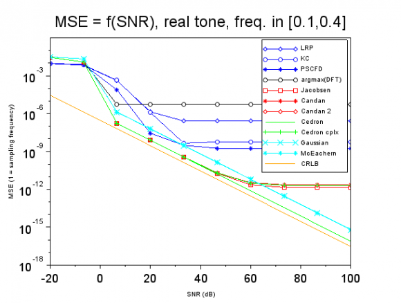
The Candan 2 formula and my complex formula are mathematically and thus numerically equivalent even though they have quite different forms. It is a bit of a exercise to show this with algebra, but it can be done. They both veer off due to being approximations while my real formula follows the CRLB line since it is exact. My improved real formula is not in that analysis.
My time domain frequency formulas, articles starting with titles "Exact Near Instantaneous Frequency Formulas" are the only ones I have which work the same for real or complex pure tones with corresponding parameters.
Why your workaround fixes the sign problem in your test code is a property of your test code, not the equations. If you want me to look at that, please start a new topic in the forum and we can discuss it further there.
Hi Ced,
you wrote "Your workaround works approximately, instead ..." and you wrote "Why your workaround fixes the sign problem in your test code ..."
So obviously you are still getting me wrong here: As written before this thread "Thread about using calculus with pure real tones" has absolutely nothing to do with fixing my sign errors I reported in the first thread "Thread about sign errors". That I use a real cosine signal instead of complex exp(i...) signal was neither intended to fix the phase sign error nor does it fix it!
Please believe me that I will follow up fixing my sign errors when I get the time in the thread "Thread about sign errors" but not here.
Please forgive me, but my purpose is not getting exact results with your formulae. Instead I want to apply it to real signals with hundreds of multi-tones in an unregular grid. The base tone is 50MHz +/-5MHz, the mean distance between all tones is 100MHz but every tone has an individual random frequency offset from -5MHz to +5MHz around the regular 100MHz grid and the final tone is 60GHz +/-5MHz. Every tone has a random phase. And as I have signals measured from real RF hardware there will be noise as well.Of course the measured tones suffer also from carrier phase noise: every tone is smeared over several bins.
So I started the second thread "Thread about using calculus with pure real tones" only to find whether it makes sense in doing so. Please tell if you don't like my application.
Thank you very much for confirming that you also get with your calculus more or less very similar results with complex tones (Sn=M*exp(i ...)) and with pure real tones (Sn=M*cos(...) ). That the magnitude of the cos is half the magnitude of the exp is fully understood.
Thanks also for emphasizing accuracy issues when my tones got close to DC or to Nyquist frequency! Fortunately this cannot happen: the bin frequency is 500kHz and the Nyquist frequency is 128GHz.
I posted a new question in the forum where you can respond, we are truly getting broader than this article's content.
Hi Ced,
thanks for all your effort!
After clearing all the confusions I'd like to close this thread for tidy communication. So I've just revised my opening post. I appreciate if you write another direct reply to it.
If you like please also revise your initial direct reply from September 23, 2022 and mark it as somehow obsolete as replaced by the new direct reply.
Best regards
echo21
To post reply to a comment, click on the 'reply' button attached to each comment. To post a new comment (not a reply to a comment) check out the 'Write a Comment' tab at the top of the comments.
Please login (on the right) if you already have an account on this platform.
Otherwise, please use this form to register (free) an join one of the largest online community for Electrical/Embedded/DSP/FPGA/ML engineers:


