


Two Easy Ways To Test Multistage CIC Decimation Filters
This blog presents two very easy ways to test the performance of multistage cascaded integrator-comb (CIC) decimation filters [1]. Anyone implementing CIC filters should take note of the following proposed CIC filter test methods.
Introduction
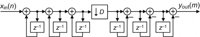
Figure 1 presents a multistage decimate by D CIC filter where the number of stages is S = 3. The '↓D' operation represents downsampling by integer D (discard all but every Dth sample), n is the input time index, and m is the output time index.
The traditional method for testing such a filter implementation is to apply to the filter a low-frequency sinusoidal xin(n) input sequence of frequency fin Hz, having N samples/cycle, and a peak amplitude of Ain. If the filter's sinusoidal yout(n) output sequence has N/D samples/cycle and the correct Aout < Ap output peak amplitude then the filter implementation is working properly. The proper Aout amplitude value depends, of course, on the [Dsin(πfinD)/sin(πfin)]S frequency magnitude response of the filter.
With that said, I propose two very simple test techniques, using unit-sample impulse and step input sequences, to supplement the traditional CIC filter test method.
The First CIC Filter Test
The unit-sample impulse response of such an S-stage decimation filter, so long as D ≥ S, will be S non-zero-valued samples followed by an all-zeros sequence. Figure 2 shows the impulse response of the Figure 1, S = 3-stage, CIC decimation filter when the decimation factor is D = 5.
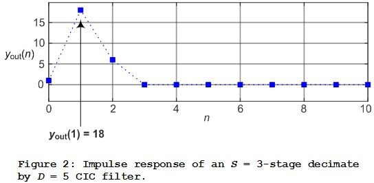
We can verify the proper operation of Figure 2's 3-stage CIC filter by simply applying an impulse xin(n) input sequence, a one followed by a string of zero-valued samples. Next we monitor the value of the filter's second, yout(1), output sample. If the filter's yout(1) output sample is equal to:

then the filter is operating properly. In Eq. (1), a term X! denotes X-factorial and 0! = 1. The derivation of Eq. (1) is given in the Appendix A.
For example using Eq. (1), Figure 2's 3-stage, D = 5, filter's yout(1) output sample being:

tells us the Figure 2 CIC filter is operating properly.
The Second CIC Filter Test
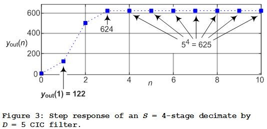
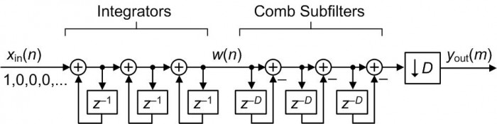
When the xin(n) input sequence to an S-stage CIC decimation filter is an all ones sequence, the filter's step response will be S samples, of various amplitudes, followed by a constant sequence of DS-valued samples. Figure 3 shows the step response of an S = 4-stage CIC decimation filter when the decimation factor is D = 5.
If the Figure 3 filter's yout(1) step response sample is equal to:

then the filter is operating properly. The derivation of Eq. (3) is given in the Appendix B.
For example using Eq. (3), Figure 3's 4-stage, D = 5, filter's yout(1) step response output sample being:

tells us the Figure 3 CIC filter is operating properly.
Conclusions
I presented two very simple computational techniques for testing multistage CIC decimation filters. The two tests comprise merely verifying, using Eqs. (1) and (3), the correct values of the second sample of the impulse and step responses of the multistage CIC decimation filter under test.

References
[1] E. Hogenauer, "An Economical Class of Digital Filters For Decimation and Interpolation," IEEE Trans. Acoust. Speech and Signal Proc., Vol. ASSP–29, pp. 155–162, April 1981.
APPENDIX A
The derivation of Eq. (1) is an interesting example of how DSP can, now and then, lead us down dark passages containing the clever work of dead mathematicians.
Assuming the reader is somewhat familiar with CIC decimation filters, the derivation of Eq. (1) proceeds as follows. The 3-stage Figure 1 decimation filter can be redrawn with downsampling as the final process as shown in Figure A-1. For a given xin(1) input, the Figure 1 and Figure A-1 filters will produce identical yout(n) output sequences.
Let's now travel back in time to the work of pioneers in the Theory of Numbers, i.e., Pascal's triangle shown in Figure A-2. Careful examination of Pascal's triangle reveals that the diagonal sequences in Figure A-2 are the impulse response sequences of a Figure A-1 multistage CIC filter's last integrator.
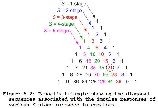
For example, the S = 3-stage diagonal sequence in Figure A-2 is the w(n) impulse response sequence for the S = 3-stage filter in Figure A-1. That is, when xin(n) is a unit sample impulse sequence, w(n) = 1,3,6,10,15, and so on.
With that said let's keep in mind that our goal is to determine the second sample, yout(1) in Figure A-1, of the decimated by D impulse responses of various multistage CIC filters. Empirical study of Pascal's triangle and the behavior of cascaded comb subfilters shows that yout(1) can be found by determining the (D+1)th number in the appropriate diagonal sequence in Figure A-2 followed by subtracting the value S from that (D+1)th number.
This all sounds a bit complicated but it's really not. For example, the yout(1) sample of a decimated by D = 5 impulse response of a 3-stage CIC filter is the 5+1 = 6th sample of the S = 3 diagonal sequence, the circled 21 in Figure A-2, minus S = 3. In this example yout(1) is 21-3 = 18. That value of 18 corresponds to the yout(1) = 18 in the above Figure 2.
OK, we're almost finished with this derivation. So, the first step in finding yout(1) of a decimated by D impulse response of an S-stage CIC filter is to determine the (D+1)th sample value in the appropriate diagonal sequence of Pascal's triangle. We do that by modifying the Binomial Theorem equation,

that computes the Ith element in the Kth row of Pascal's triangle. Our modification to Eq. (A-1) to find the (D+1)th sample value in the Sth diagonal sequence of Figure A-2's Pascal's triangle is:

Subtracting S from Eq. (A-2) yields our desired expression for the yout(1) sample of a decimated by D impulse response of an S-stage CIC filter as:

completing our derivation of Eq. (1).
APPENDIX B
The derivation of Eq. (3), finding an expression for computing the yout(1) sample of a decimated by D step response of various multistage CIC filters, proceeds in the same way we derived Eq. (1) in Appendix A. First we examine Pascal's triangle to determine the diagonal sequences associated with the step responses of various S-stage cascaded integrators. This enables us to draw Figure B-1 where, for example, the S = 3-stage diagonal sequence in Figure B-1 is the w(n) step response sequence for the S = 3-stage filter in Figure A-1. That is, when the Figure A-1 xin(n) input is an all ones sequence, the last integrator's step response output is w(n) = 1,4,10,20,35, and so on.
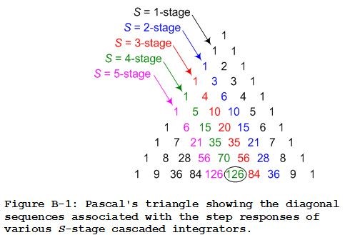
Again, empirical study of Figure B-1's Pascal's triangle and the behavior of cascaded comb subfilters reveals that our desired yout(1) sample of a decimated by D step response of an S-stage CIC filter can be found by determining the (D+1)th number in the appropriate diagonal sequence in Figure B-1 followed by subtracting the value S from that (D+1)th number.
As an example of finding a yout(1) step response output sample, the yout(1) sample of a decimated by D = 5 step response of a 4-stage CIC filter is the 5+1 = 6th sample of the S = 4 diagonal, the circled 126 in Figure B-1, minus S = 4. So the yout(1) sample of a decimated by D = 5 step response of a 4-stage CIC filter is 126-4 = 122. That value of 122 corresponds to the yout(1) = 122 in the above Figure 3.
Modifying the Binomial Theorem Eq. (A-1), our equation for computing the (D+1)th sample value in the Sth diagonal sequence of Figure B-1's Pascal's triangle is:

Subtracting S from Eq. (B-1) gives the desired expression for the yout(1) sample of a decimated by D step response of an S-stage CIC filter as:

completing our derivation of Eq. (3).


- Comments
- Write a Comment Select to add a comment

Hi Rick,
Thanks for the article.
I will add my case as "FPGA based DSP" engineer rather than software dsp engineer.
(1) Algorithm stage: I start with a software model (MATLAB) for above CIC structure. I will match the model with the intended fpga bitwidth/truncation/rounding...etc.
I study my cic model in MATLAB for dsp functionality. That could be based on an impulse or random input stream or some specific in-house input vectors. As such I don't need to prove its concept but rather see my model is behaving as expected.
Once I am happy I will inject it with random input of proper dynamic range and get reference output possibly for mega samples.
(2) Implementation stage: I only pass that random input and check output is identical bit true with model Here clocking and sampling are in action but output must match.
I do not need to retest the fpga implementation dsp wise.
Be it simulation or actual hardware.
and sign off...
This applies to any function or chain of functions.

Hi Kaz. Thanks for your comments.
To post reply to a comment, click on the 'reply' button attached to each comment. To post a new comment (not a reply to a comment) check out the 'Write a Comment' tab at the top of the comments.
Please login (on the right) if you already have an account on this platform.
Otherwise, please use this form to register (free) an join one of the largest online community for Electrical/Embedded/DSP/FPGA/ML engineers:


