


Half-band filter on Xilinx FPGA
1. DSP48 Slice in Xilinx FPGA
There are many DSP48 Slices in most Xilinx® FPGAs, one DSP48 slice in Spartan6® FPGA is shown in Figure 1, the structure may different depending on the device, but broadly similar.
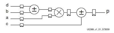
Figure 1: A whole DSP48A1 Slice in Spartan6 (www.xilinx.com)
2. Symmetric Systolic Half-band FIR
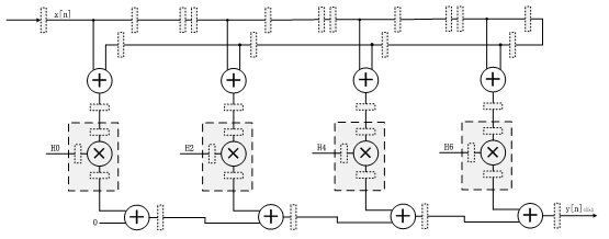
Figure 2: Symmetric Systolic Half-band FIR Filter
3. Two-channel Symmetric Systolic Half-band FIR
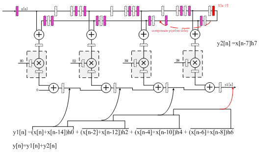
Figure 3: 2-Channel Symmetric Systolic Half-band FIR Filter
y1[n] =(x[n]+x[n-14])h0 + (x[n-2]+x[n-12])h2 + (x[n-4]+x[n-10])h4 + (x[n-6]+x[n-8])h6
y2[n] =x[n-7]h7
y[n]=y1[n]+y2[n]
4. Advantages and Disadvantages
The symmetric systolic FIR filter is considered an optimal solution for parallel filter architectures.
The advantages to using the Systolic FIR filter are:
- Highest Performance: Maximum performance can be achieved with this structure because there is no high fanout input signal. Larger filters can be routing-limited if the number of coefficients exceeds the number of DSP slices in a column on a device.
- Efficient Mapping to the DSP48 Slice: Mapping is enabled by the adder chain structure of the Systolic FIR Filter. This extendable structure supports large and small FIR filters.
- No External Logic: No external FPGA fabric is required, enabling the highest possible performance.
The disadvantage to using the Systolic FIR filter is:
- Higher Latency: The latency of the filter is a function of how many coefficients are in the filter. The larger the filter, the higher the latency:
from Log2N (add tree) to N (Systolic) : N is the number of multiplies.
5. Rounding
The number of bits on the output of the filters must be reduced to a manageable width.Truncation introduces an undesirable DC data shift due to the nature of two’s complement numbers. The DC shift can be improved with the use of symmetric rounding, where positive numbers are rounded up and negative numbers are rounded down.
The rounding is achieved in the following manner:
For positive numbers: Binary Data Value + 0.10000...and then truncate
For negative numbers: Binary Data Value + 0.01111... and then truncate
/**************************************************************
module name : Half_band_fir_down2
version : 0.3
author : Lyons Zhang ( fpgaplayer@gmail.com )
description : 2-Channel interleaved input/output half-band filter downsample 2 ,the filter is a little long,because I'd like to show the original appearance of the practical application.
revision history:
---------------------------------------------------------------
1. 2010-11-11, initial version
2. 2010-11-30, second version, revise by advice of old cfelton
3. 2011-03-28, third version, symmetric rounding used to improved DC shift
---------------------------------------------------------------
//coefficient of Half Band Filter : ( 1,14,14 )
//output data of Half Band Filter : ( 2,28,24 ) ---> ( 1,14,10 )
***************************************************************/
`timescale 1ns/1ps
module Half_band_fir_down2
(
//input signals
Clk, //FPGA's master clock
Reset, //Global reset
Data_in_0, //Data_in_0 rate is Clk/2
Data_in_1, //Data_in_1 rate is Clk/2
Index, //Index reverse every Clk period
//output signals
Data_out_0, //Data_out_0 rate is Clk/4
Data_out_1, //Data_out_1 rate is Clk/4
Hb_overflow_0, //Indicate filter overflow, be of use in practise
Hb_overflow_1 //Indicate filter overflow, be of use in practise
);
/*****************************************************/
/*--- Input and Output Ports declaration -----*/
/*****************************************************/
input Clk;
input Reset;
input [14:0] Data_in_0;
input [14:0] Data_in_1;
input Index;
output [13:0] Data_out_0;
output [13:0] Data_out_1;
output Hb_overflow_0;
output Hb_overflow_1;
/*****************************************************/
/*------- Ports Type declaration --------*/
/*****************************************************/
reg [13:0] Data_out_0;
reg [13:0] Data_out_1;
reg Hb_overflow_0;
reg Hb_overflow_1;
/*****************************************************/
/*------- parameter declaration --------*/
/*****************************************************/
//Coefficients of half band filter
parameter Coef_c0_c46 = -17'd8;
parameter Coef_c2_c44 = 17'd27;
parameter Coef_c4_c42 = -17'd68;
parameter Coef_c6_c40 = 17'd146;
parameter Coef_c8_c38 = -17'd281;
parameter Coef_c10_c36 = 17'd499;
parameter Coef_c12_c34 = -17'd837;
parameter Coef_c14_c32 = 17'd1353;
parameter Coef_c16_c30 = -17'd2161;
parameter Coef_c18_c28 = 17'd3547;
parameter Coef_c20_c26 = -17'd6561;
parameter Coef_c22_c24 = 17'd20727;
parameter Coef_c23 = 17'd32768;
/*****************************************************/
/------ Variable declaration --------*/
/*****************************************************/
wire [14:0] Add_a[11:0];
wire [14:0] Add_d[11:0];
wire [32:0] Add_c[11:0];
wire [16:0] Mult_b[11:0];
wire [33:0] Dsp_r[11:0];
reg [14:0] Data_in_reg[92:0];
reg [33:0] Data_result; //Expand to 34 bits not only avoid overflow,
wire [33:0] Data_result_carry; //But also for several gains by cut different LSBs
reg Index_1;
reg [13:0] Data_out_0_reg;
/*****************************************************/
/*------- Main Code --------*/
/*****************************************************/
always @ ( posedge Clk or posedge Reset )
begin
if ( Reset == 1'b1 )
Data_in_reg[0] <= 15'b0;
else if ( Index == 1'b1 )
Data_in_reg[0] <= Data_in_0;
else
Data_in_reg[0] <= Data_in_1;
end
genvar Numd;
generate
for (Numd = 1; Numd <= 92; Numd = Numd + 1)
begin : U_data_in_reg
always @ ( posedge Clk or posedge Reset )
begin
if ( Reset == 1'b1 )
Data_in_reg[Numd] <= 15'b0;
else
Data_in_reg[Numd] <= Data_in_reg[Numd-1];
end
end
endgenerate
//adder A between DSPs has 5 registers
assign Add_a[0] = Data_in_reg[0];
assign Add_a[1] = Data_in_reg[5];
assign Add_a[2] = Data_in_reg[10];
assign Add_a[3] = Data_in_reg[15];
assign Add_a[4] = Data_in_reg[20];
assign Add_a[5] = Data_in_reg[25];
assign Add_a[6] = Data_in_reg[30];
assign Add_a[7] = Data_in_reg[35];
assign Add_a[8] = Data_in_reg[40];
assign Add_a[9] = Data_in_reg[45];
assign Add_a[10] = Data_in_reg[50];
assign Add_a[11] = Data_in_reg[55];
//adder D between DSPs has 3 registers
assign Add_d[0] = Data_in_reg[92];
assign Add_d[1] = Data_in_reg[89];
assign Add_d[2] = Data_in_reg[86];
assign Add_d[3] = Data_in_reg[83];
assign Add_d[4] = Data_in_reg[80];
assign Add_d[5] = Data_in_reg[77];
assign Add_d[6] = Data_in_reg[74];
assign Add_d[7] = Data_in_reg[71];
assign Add_d[8] = Data_in_reg[68];
assign Add_d[9] = Data_in_reg[65];
assign Add_d[10] = Data_in_reg[62];
assign Add_d[11] = Data_in_reg[59];
//Add_c
assign Add_c[0] = 33'b0;
assign Add_c[1] = Dsp_r[0][32:0];
assign Add_c[2] = Dsp_r[1][32:0];
assign Add_c[3] = Dsp_r[2][32:0];
assign Add_c[4] = Dsp_r[3][32:0];
assign Add_c[5] = Dsp_r[4][32:0];
assign Add_c[6] = Dsp_r[5][32:0];
assign Add_c[7] = Dsp_r[6][32:0];
assign Add_c[8] = Dsp_r[7][32:0];
assign Add_c[9] = Dsp_r[8][32:0];
assign Add_c[10] = Dsp_r[9][32:0];
assign Add_c[11] = Dsp_r[10][32:0];
//Mult_b are filter coefficient
assign Mult_b[0] = Coef_c0_c46;
assign Mult_b[1] = Coef_c2_c44;
assign Mult_b[2] = Coef_c4_c42;
assign Mult_b[3] = Coef_c6_c40;
assign Mult_b[4] = Coef_c8_c38;
assign Mult_b[5] = Coef_c10_c36;
assign Mult_b[6] = Coef_c12_c34;
assign Mult_b[7] = Coef_c14_c32;
assign Mult_b[8] = Coef_c16_c30;
assign Mult_b[9] = Coef_c18_c28;
assign Mult_b[10] = Coef_c20_c26;
assign Mult_b[11] = Coef_c22_c24;
//* (A+D)*B+C
//14 pipelines
genvar Num;
generate
for (Num = 0; Num <= 11; Num = Num + 1)
begin : U_DDC_HF2_DSP
DDC_HF2_DSP DDC_HF2_DSP
(
//* Inputs
.clk ( Clk ),
.a ( Add_a[Num] ),
.d ( Add_d[Num] ),
.b ( Mult_b[Num] ),
.c ( Add_c[Num] ),
//* Outputs
.p ( Dsp_r[Num] )
);
end
endgenerate
//Data_in_reg_57 add 3 pipelines
always @ ( posedge Clk or posedge Reset )
begin
if ( Reset == 1'b1 )
Data_result <= 34'd0;
else
Data_result <= Dsp_r[11] + { {4{Data_in_reg[60][14]}},Data_in_reg[60],15'b0 };
end
assign Data_result_carry = ( Data_result[33]== 1'b0 ) ? ( Data_result + 34'h000010000 ) : ( Data_result + 34'h00000ffff ); //Symmetric Rounding
always @ ( posedge Clk or posedge Reset )
begin
if ( Reset == 1'b1 )
Index_1 <= 1'b0;
else if ( Index == 1'b0 )
Index_1 <= ~Index_1;
else
;
end
always @ ( posedge Clk or posedge Reset )
begin
if ( Reset == 1'b1 )
Data_out_0_reg <= 14'b0;
else if ( ( Index == 1'b1 ) && ( Index_1 == 1'b1 ) )
begin
if ( ( Data_result_carry[33:30] == 4'b0000 ) || ( Data_result_carry[33:30] == 4'b1111 ) )
Data_out_0_reg <= Data_result_carry[30:17];
else if ( Data_result_carry[33] == 1'b0 )
Data_out_0_reg <= 14'h1fff;
else
Data_out_0_reg <= 14'h2000;
end
else
;
end
always @ ( posedge Clk or posedge Reset )
begin
if ( Reset == 1'b1 )
Data_out_0 <= 14'b0;
else
Data_out_0 <= Data_out_0_reg;
end
always @ ( posedge Clk or posedge Reset )
begin
if ( Reset == 1'b1 )
Data_out_1 <= 14'b0;
else if ( ( Index == 1'b0 ) && ( Index_1 == 1'b1 ) )
begin
if ( ( Data_result_carry[33:30] == 4'b0000 ) || ( Data_result_carry[33:30] == 4'b1111 ) )
Data_out_1 <= Data_result_carry[30:17];
else if ( Data_result_carry[33] == 1'b0 )
Data_out_1 <= 14'h1fff;
else
Data_out_1 <= 14'h2000;
end
else
;
end
always @ ( posedge Clk or posedge Reset )
begin
if ( Reset == 1'b1 )
Hb_overflow_0 <= 1'b0;
else if ( ( Index == 1'b1 ) && ( Index_1 == 1'b1 ) )
begin
if ( ( Data_result_carry[33:30] == 4'b0000 ) || ( Data_result_carry[33:30] == 4'b1111 ) )
Hb_overflow_0 <= 1'b0;
else
Hb_overflow_0 <= 1'b1;
end
else
;
end
always @ ( posedge Clk or posedge Reset )
begin
if ( Reset == 1'b1 )
Hb_overflow_1 <= 1'b0;
else if ( ( Index == 1'b0 ) && ( Index_1 == 1'b1 ) )
begin
if ( ( Data_result_carry[33:30] == 4'b0000 ) || ( Data_result_carry[33:30] == 4'b1111 ) )
Hb_overflow_1 <= 1'b0;
else
Hb_overflow_1 <= 1'b1;
end
else
;
end
endmodule
/*****************************************************/
/*------- the end --------*/
/*****************************************************/
In the codes I use DSP48 as figure 4.
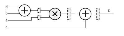
figure 4 DDC_HF2_DSP(generated by DSP48) in the code
References:
[1]www.xilinx.com, DSP:Designing for Optimal Results,2005.


- Comments
- Write a Comment Select to add a comment


To post reply to a comment, click on the 'reply' button attached to each comment. To post a new comment (not a reply to a comment) check out the 'Write a Comment' tab at the top of the comments.
Please login (on the right) if you already have an account on this platform.
Otherwise, please use this form to register (free) an join one of the largest online community for Electrical/Embedded/DSP/FPGA/ML engineers:


