


Implementing a full-duplex UART using the TMS320VC33 serial port
Although the TMS320VC33 serial port was designed to be used as a synchronous port, it can also be used as an asynchronous port under software control. This post describes the hardware and software needed to use a TMS320VC33 serial port as a full-duplex UART port. A schematic diagram and a lengthy code listing are provided to illustrate the solution. This note discusses the implementation of an interrupt-driven, full-duplex, asynchronous serial interface, 9600-baud UART with 8 data bits, 1 stop bit, and no parity using the on-chip resources of the TMS320VC33.
How do I develop a full-duplex, universal asynchronous receive transmit serial interface using the on-chip serial port of the TMS320VC33?
By using the DR0, DX0 pins in conjunction with serial port receive/transmit timers and an external interrupt, one can develop a very flexible full-duplex UART in software, as shown in Figure 1.
This design relies on the fact that received RS-232 signals always start with a “start bit” that is not part of the data, and end with one or more “stop bits” that are also not part of the data. This design keeps the receiver turned off and an interrupt (also tied to the receive line) turned on when not receiving a character.
The receive sequence begins when the start bit triggers the external interrupt. At the interrupt service routine, c_receive0, the code turns the interrupt off and the receiver on. Then the CPU samples DR0; the data comes in as a normal 8-bit character.
When serial data is input, the receiver shifts the bits into the receive-shift register (RSR). When the specified number of bits are shifted in, the data-receive register (DRR) is loaded from RSR, and the RRDY status bit is set.
After the received byte is processed, the external interrupt is then re-enabled and the system waits for the next start bit.
The stop bits assure the TMS320VC33 has time to handle the data before the next character.
The transmitter basically frames the data into 8-bit words, adding a start bit, the character to send, and the stop bit. The transmitter then waits until it is free, after which it sends the data. The serial port is set up as a continuous transmit normal port. Frame syncs are not used and internal clocks are used for the serial port timing; these are timed with the TMS320VC33 clock and need to be adjusted if clock rates change.
A more efficient (but more complicated) design definitely could be done.
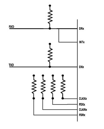
Figure 1. Note that the received signal is tied to DR0 (Data Receive) and also INTx (any of the TMS320VC33 interrupts). The clocks and frame syncs are not used.
Code
gl_prt_cnt .word 068004c4h ; Initial setup for the serial port
; status register. This sets the
; following things:
; FSX is output.
; Fixed data rate signalling
; Standard frame sync mode
; Internal xmit clk
; Internal rec clk
; Active high DX and DR
; XLEN - 8 bits
; RLEN - 8 bits
; Transmitter interrupt enabled
; Receive interrupt enabled
; Activate the transmitter
; Deactivate the receiver
x_prt_cnt .word 00000111h ; Setup for the transmit port control
; register. Set all the transmit
; pins as serial port pins.
r_prt_cnt .word 00000111h ; Setup for the receive port control
; register. Set all the receive
; pins as serial port pins.
tmr_cnt .word 0000003cfh ; Setup for the timer control reg.
; Starts the timer
; Free run the timer (no hold)
; Clock mode
; Internal clock source
tmr_per .word 028b128b1h ; Timer periods. This is 10417 for
; the receiver, which is a little
; slow. This makes sure we don’t
; shift in time before the bits.
; These also assume a 150MHZ clock
; in the VC33; these values will have
; to be adjusted for different clock
; rates.
enab_int .word 000000031h ; Enable serial xmit, serial recieve,
; and int 0 for serial port stuff.
first_xmt .word 00000ffffh
rec_ser_cnt .word 808040h ; Address of serial port status register
s_recc_int .word 000000001h ; Mask for the receive interrupt (int0)
c_recc_int .word 0fffffffeh ; Inverted mask to clear the rec int (int0)
reset_rec .word 0f7ffffffh ; Mask to write a 0 to the rec reset
unreset_rec .word 008000000h ; Unreset the receiver.
.text
_init_io
LDP @rec_ser_cnt,DP
LDI @rec_ser_cnt,AR0
LDI @x_prt_cnt,R0 ; Set up the transmit control port.
STI R0,*+AR0(2)
LDI @r_prt_cnt,R0 ; Set up the receive control port.
STI R0,*+AR0(3)
LDI @tmr_per,R0 ; Set the timer period register.
STI R0,*+AR0(6)
LDI @tmr_cnt,R0 ; Set the timer control register.
STI R0,*+AR0(4)
LDI @gl_prt_cnt,R0 ; Set the global serial control register.
STI R0,*+AR0(0)
OR 2000h,ST ; Enable CPU interrupts globally
OR @enab_int,IE ; Enable interrupts.
LDI @first_xmt,R0 ; Start the transmitter sending 1’s
STI R0,*+AR0(8)
RETS
;* c_sp0intTra - handle an interrupt from the serial port transmitter.
c_sp0intTra
PUSH R0
PUSH DP
PUSH AR0
CALL _flip8 ; data to be transferred to serial port is
; supposed to be already loaded in R0
STI R0,*+AR0(8)
POP AR0
POP DP
POP R0
POP ST
RETI
;* c_int0Rec - This interrupt handle is called by INT0. It is tied to the
;* receive data line, it will be called when the start bit is received
;* for a character of information. It will turn on the serial receiver
;* (and the serial receiver interrupt) and turn its own interrupt off.
c_int0Rec
PUSH ST
PUSH R0
PUSH DP
PUSH AR0
LDP @rec_ser_cnt,DP
LDI @rec_ser_cnt,AR0
AND @c_recc_int,IE ;do not allow the receive coming interrupt
LDI *+AR0(0),R0 ;Ready the receiver
OR @unreset_rec,R0
STI R0,*+AR0(0)
POP AR0
POP DP
POP R0
POP ST
RETI
;* c_sp0intRec - Handle an interrupt from the serial port receiver to inform it
;* of the receipt of a byte on the serial port. This routine will
;* turn off the receiver and restore the interrupt telling it that
;* a byte is about to come.
c_sp0intRec
PUSH ST
PUSH R0
PUSH DP
PUSH AR0
LDP @rec_ser_cnt,DP
LDI @rec_ser_cnt,AR0
LDI *+AR0(0),R0 ;Reset the receiver
AND @reset_rec,R0
STI R0,*+AR0(0)
AND @c_recc_int,IF ;clear receive coming interrupt
OR @s_recc_int,IE ;enable the interrupt for the next byte
LDI *+AR0(0xC),R0 ;data received at 0x80804c
CALL _flip8 ;data from RS-232 is backwards, flip it around
POP AR0
POP DP
POP R0
POP ST
RETI
This code assumes all interrupts services routines are installed.
Reference
[1] "TMS320C3x User’s Guide". Texas Instruments. Julio 1997-SPRU031E.
[2] "TMS320C3x General-Purpose Applications". Texas Instruments. Julio 1997-SPRU194.


- Comments
- Write a Comment Select to add a comment

To post reply to a comment, click on the 'reply' button attached to each comment. To post a new comment (not a reply to a comment) check out the 'Write a Comment' tab at the top of the comments.
Please login (on the right) if you already have an account on this platform.
Otherwise, please use this form to register (free) an join one of the largest online community for Electrical/Embedded/DSP/FPGA/ML engineers:


