


Modeling the Lips and Mouthpiece
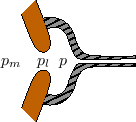
Figure 9.58 depicts a schematic of a brass-player's lips
positioned within a mouthpiece. The air pressure10.22 is denoted ![]() inside the mouth,
inside the mouth, ![]() between the lips, and
between the lips, and
![]() within the mouthpiece cup.
within the mouthpiece cup.
A simple first approximation is to assume that the air flow through the lips is inviscid (``frictionless'') and incompressible. In this case, the pressure between the lips is governed by Bernoulli's equation (see §B.7.4):
Following Cullen et al. [98] and previous researchers
[159,161],
one may assume that the flow between the lips creates a jet in the
mouthpiece having velocity ![]() . The pressure within the jet is
therefore
. The pressure within the jet is
therefore ![]() , the same as between the lips. The jet is assumed to
mix turbulently with the air in the mouthpiece so that it dissipates
its energy without raising pressure in the mouthpiece.10.23
, the same as between the lips. The jet is assumed to
mix turbulently with the air in the mouthpiece so that it dissipates
its energy without raising pressure in the mouthpiece.10.23
One- and two-mass models were also developed by Rodet and Vergez [388,533]. An early one-mass, ``swinging door'' model that works surprisingly well is in Cook's HosePlayer [89] and and TBone [88]. It is also used in the Brass.cpp patch in the Synthesis Tool Kit [91]; in this simplified model, the lip-valve is modeled as a second-order resonator whose output is squared and hard-clipped to a maximum magnitude.
The acoustic tube in a horn can be modeled as a simple digital waveguide [22,37,436,506,528], whether it is cylindrical or conical. More complicated, flaring horn sections may be modeled as two-port digital filters which provide the appropriate reflection and transmission from the bell [39,50,71,118,406,528]. Section 9.7.2 below summarizes a particularly economical approach to brass bell modeling.
It is known that nonlinear shock waves occur in the bore for large amplitude vibrations [198,341]. A simple nonlinear waveguide simulation of this effect can be implemented by shortening the delay elements slightly when the instantaneous amplitude is large. (The first-order effect of air nonlinearity in large-amplitude wave propagation is an increase in sound speed at very high pressures [52].)
It is also known that the bores of ``bent horns,'' such as the trumpet, do not behave as ideal waveguides [425]. This is because sharp bends in the metal tube cause some scattering, and mode conversion at high frequencies. Such points along the horn can be modeled using high-frequency loss and reflection.
Next Section:
Bell Models
Previous Section:
Linear Commuted Bowed Strings


