


Project update-1 : Digital Filter Blocks in MyHDL and their integration in pyFDA
This blog post presents the progress made up to week 5 in my GSoC project “Digital Filter blocks and their integration in PyFDA”. Progress was made in two areas of the project.
This post will primarily discuss filter block implementation. The interface will be discussed in a later post once further progress is made.
Direct form-I FIR filter
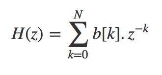
The equation specifies the direct form I implementation. It consists of a collection of a tapped delay line, adders and multipliers. The operands presented to each multiplier is a FIR coefficient, also referred to as 'tap weight'.
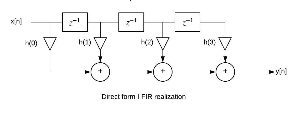
An FIR filter of order N is characterised by N+1 coefficients and, in general, require N+1 multipliers and N two-input adders. Although the implementation is reasonably straightforward behavioural model as one would expect, there were certain aspects that needed to be addressed. Since the filter parameters including order and filter coefficients are to be passed from PyFDA, the architecture is written independent of all parameters. This means the number of adders, multipliers and registers are not determined beforehand but inferred from the order.
The following is a code snippet of the behavioural model for direct form I fir filter. N delay (feed forward) blocks are created in the first loop, The multiplication and addition operations are taken care of by the second loop. This could be used to create a filter of any order N.
 @hdl.always(clock.posedge)
    def beh_direct_form_one():
        if x.valid:
            # create N feed-forward (ffd) blocks
            for i in range(N-1):
                ffd[i+1].next = ffd[i]

            ffd[0].next = x
            c = b[0]
            sop = x*c

            # sum-of-products loop
            for ii in range(N):
                c = b[ii+1]
                sop = sop + (c * ffd[ii])

            #accumulator
            yacc.next = sop
'x' is the input signal, 'b' is the list of coefficients of H(z), 'yacc' (accumulator) contains the final output of the filter.
Cascaded IIR/FIR filter
For both FIR and IIR implementations, the respective transfer function is broken up into a series of first/second order sections. For example, for an FIR filter, the equation
Is broken up into
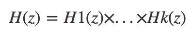
Where H1(z), H2(z),.. Hk(z) are second order sections.
For k = 2
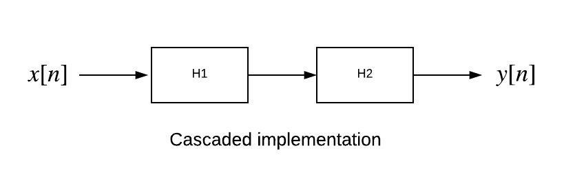
Generating the coefficients for all the second order sections is done in pyFDA. The code for Cascaded IIR filter was already present in the filter-blocks repository. I implemented the same for FIR filters. The important thing here was to understand how the series of second order sections are connected using structural modelling. A cascaded FIR filter of order N contains N+1 multipliers and N two-input adders.
'filter _iir_sos' is a function which contains behavioural description of second order iir filter and is defined as follows:
@hdl.block
def filter_iir_sos(glbl, sigin, sigout, b, a):
    # behavioural description of second order filter
'sigin' and 'sigout' are input and output signals. 'b' and 'a' are lists of numerator and denominator coefficients of second order H(z) respectively. The series of second order sections are connected using structural modelling as follows:
for ii in range(len(b)):
    list_of_insts[ii] = filter_iir_sos(
        glbl, xb[ii], xb[ii+1],
        b=tuple(map(int, b[ii])), a=tuple(map(int, a[ii])),
     )
Here ‘b’ and ‘a’ are matrices which contain coefficients of all second order sections. Each row of the matrix contains the coefficients for each second order section. The number of second order sections to be defined is inferred from length (number of rows) of matrix b.
The cascaded FIR might not actually have practical value in implementation but that was not the major concern.
Parallel IIR filter
The general idea is to break the filter transfer function into a parallel sum of first and/or second-order sections. IIR filter transfer function can be expressed as:
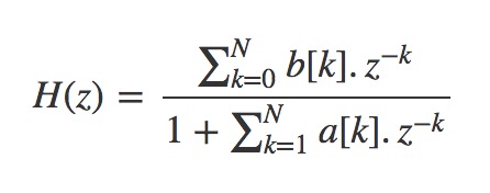
Using partial fraction expansion the transfer function is broken up into:
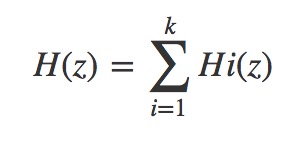
Where H1(z), H2(z).. Hk(z) are second order sections.
For k=3, the figure is shown below.
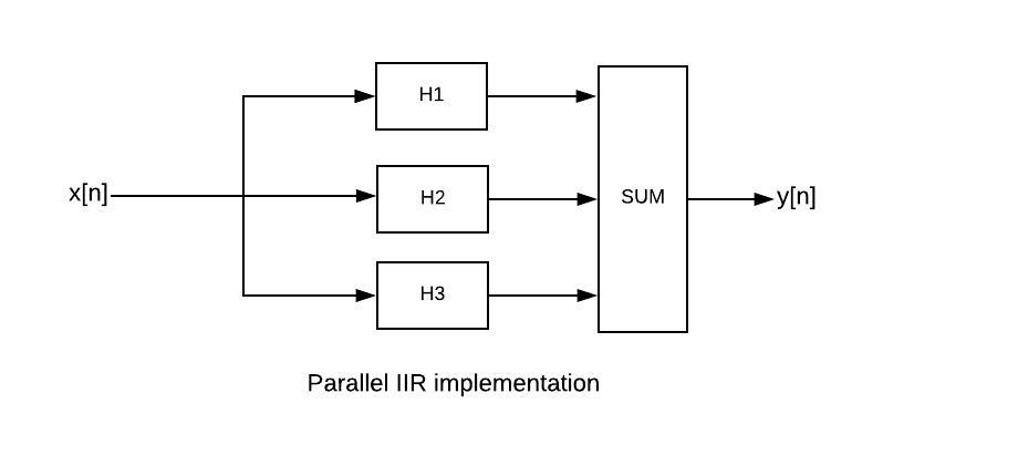
The partial fraction expansion and generating the coefficients for all the second order sections is done in pyFDA. An IIR parallel filter of order N requires 2N+1 multipliers and 2N two-input adders for implementation.
There were a few things to consider when implementing the filter in MyHDL. Each of the individual parallel IIR filters are designed as MyHDL blocks and the outputs of each of these blocks are fed into another block where they are added up as shown in the figure. While each individual block is written using behavioural model, the blocks are connected using structural modeling similar to the procedure described above.
Suppose we have a system with N parallel IIR blocks. All N output signals have to be concatenated into a single signal vector before they can be passed to the next HDL block where they are summed up. The procedure is described here.
As mentioned earlier, the architecture is independent of all filter parameters as they are inferred from PyFDA.
All examples, code snippets discussed are present in the filter-blocks repository on GitHub.


- Comments
- Write a Comment Select to add a comment
To post reply to a comment, click on the 'reply' button attached to each comment. To post a new comment (not a reply to a comment) check out the 'Write a Comment' tab at the top of the comments.
Please login (on the right) if you already have an account on this platform.
Otherwise, please use this form to register (free) an join one of the largest online community for Electrical/Embedded/DSP/FPGA/ML engineers:


