Pulse Shaping in Single-Carrier Communication Systems
Some common conceptual hurdles for beginning communications engineers have to do with "Pulse Shaping" or the closely-related, even synonymous, topics of "matched filtering", "Nyquist filtering", "Nyquist pulse", "pulse filtering", "spectral shaping", etc. Some of the confusion comes from the use of terms like "matched filter" which has a broader meaning in the more general field of signal processing or detection theory. Likewise "Raised Cosine" has a different meaning or application in this context than it does in windowing for Fourier Transforms. Some of the confusion comes from focusing on one end (either the modulator or demodulator) or one aspect of the system when a full system perspective is more helpful in understanding the issues. This article attempts to shed some light on the basic concepts behind "Pulse Shaping" in the context of single-carrier communication systems so that beginners, or experienced engineers in non-communications disciplines, can avoid some of the pitfalls that commonly hinder pilgrims early on their journey into the world of communications technology.
The fundamental job of an electronic communications system is to convey information from one place to another reliably through what may be a treacherous channel. Typical channel impairments include thermal noise in the receiving amplifiers, reflections due to impedance mismatches in wired channels or multipath propagation in wireless channels, interference due to other rf-energy-emitting devices, frequency selectivity due to imperfect cabling or components, and other component-related distortions. "Digital" single-carrier communication systems typically convey information by transmitting periodic pulses modulated in amplitude, phase, frequency, or some combination thereof. An obvious selection of a basic candidate transmission system is to use rectangular pulses modulated in binary amplitude, i.e., the typical Non-Return to Zero (NRZ) bit stream. Figure 1 shows an example bit stream modulated in NRZ fashion with a periodic "symbol" period of Ts. Information encoded in binary as ones and zeros (or, for those so inclined, marks and spaces) is transmitted at symbol rate of Rs = 1/Ts. The amplitude is modulated at either level A or level B, which could be different levels of voltage, or pressure, or whatever physical attribute can be measured in the transmission medium at the receiver. For the common case of interest to us here, i.e., electronic communication systems, this modulation is usually realized as a voltage change. The "pulses" are "rectangular" simply because of their geometric shape within the stream, holding a constant amplitude at either the A or B levels for a duration of Ts. Often, and for our purposes here, B = -A.

Figure 1. A binary bit stream modulated as an NRZ signal with rectangular pulses.
When the NRZ, rectangular-pulse bit stream is transmitted with a sufficiently random bit stream it will exhibit an average transmit spectrum that is the Fourier transform of the basic pulse shape. In this case the FT of a rectangle creates a sinx/x envelope, as shown in Figure 2. An important caveat is that this spectrum will be observed at the output of the transmitter only if there is sufficient entropy, or randomness, in the bit stream. Patterns in the bit stream can change the output spectrum and this is easily imagined by considering that a constant stream of ones or zeros, i.e., an unmodulated DC level, will exhibit a spike at DC rather than the sinx/x response. Likewise an alternating one-zero pattern, like a clock sequence, will exhibit two spikes spaced equally on either side of DC at the transition rate which is half the symbol rate. So generally when we speak of the transmit spectrum associated with a pulse shape we are assuming that there is enough randomness, or entropy, in the modulated sequence that the pathological cases or pattern dependence are avoided. This is actually usually the case in real world applications as well for a number of reasons.
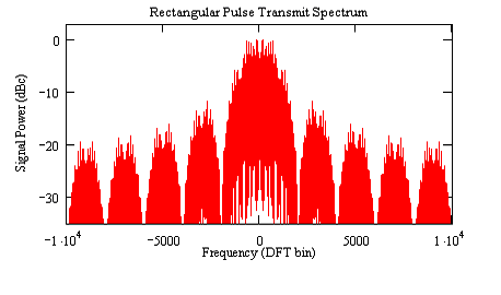 s = 20000 and Rs = 2000. For rectangular symbols the spectral nulls are spaced from the center of the main lobe at Rs intervals, or every 2000 bins in this case." align="middle" border="0">
Figure 2. Shown is the transmit spectrum for a vector of length 20000 samples of rectangular pulses ten samples long and randomly modulated with a binary stream. Generally the main lobe of a single-carrier spectrum will have a 3dB bandwidth equal to the symbol rate. In this case fs = 20000 and Rs = 2000. For rectangular symbols the spectral nulls are spaced from the center of the main lobe at Rs intervals, or every 2000 bins in this case.
In the receiver a rectangular pulse is optimally detected with an integrate-and-dump filter. Intuitively, this works by integrating the energy over the symbol period, and only over the duration of the current symbol (i.e., not integrating energy from adjacent symbols). It is the job of the timing recovery loop in the demodulator to assure that the integrator period is synchronized in time to the received symbol period. How to accomplish that is out of the scope of this article but is well understood and covered in many texts and articles on digital communications. A simple analysis of such a structure, shown in Figure 3, reveals that the frequency response of an integrate-and-dump filter, which is essentially a Moving Average boxcar filter, exactly matches the sinx/x spectral shape of the transmitted signal. It is, therefore, an optimally matched filter to detect the transmitted pulses.
The rectangular-pulse case is an interesting case in that the transmitted symbols naturally maintain time orthogonality to each other. If the channel is memoryless, i.e., there are no significant reflections or dispersion, then this time orthogonality will guarantee that there is no Inter-Symbol-Interference (ISI) in the receiver. In other words, the energy from adjacent symbols will not interfere with the current symbol being detected. ISI degrades performance since the energy of the interfering symbol may create an erroneous detection of the current symbol.
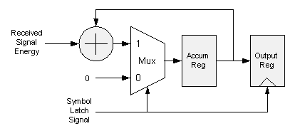
Figure 3. Integrate-and-Dump filter for receiving rectangular pulses. The Symbol Latch Signal simultaneously resets the Accumulator Register for the next symbol and latches the current accumulated symbol energy in the Output Register. The accumulator is run at a system clock rate N-times higher than the symbol rate.
There are some notable disadvantages to the use of rectangular pulses. It can be observed in Fig. 2 that it would be difficult to put two channels, or two instances of the spectrum, very close to each other in frequency without the sidelobe energy interfering with each other. The width of the mainlobe is also pretty significant compared to the symbol rate. Since available spectrum is often a valuable resource, the use of rectangular pulses is generally a poor use of the spectral resources due to the wide spectrum occupancy and poor spectral efficiency. An additional consequence of this is that the receiver bandwidth, since it is matched to the transmit signal, is also quite wide and will therefore admit more noise and interference than may otherwise be desirable.
In order to provide better "channelization", or the ability to stack multiple channels next to each other while minimizing inter-carrier or inter-channel interference, as well as minimizing the noise bandwidth in the receiver, better filtering methods are needed. A key criterion for an improved filter is that the time orthogonality of the symbols is still maintained, i.e., the filter does not cause ISI. Since generally a digital system has a pretty easy time of sampling a small instant of time, it is really only necessary for that time orthogonality property to be maintained in the receiver at the critical sampling point. Figure 4 illustrates this design requirement graphically.
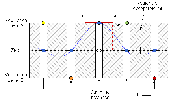
Figure 4. Shown are transmitted binary symbols of various colors. The blue dots illustrate that if the symbol is spread out over time, in order to allow a narrower transmit spectrum, it will not interfere with the sampling of adjacent symbols as long as its impulse response is zero at those sampling instants. The center blue dot represents the modulated information for that symbol, and the rest of the blue dots are that symbol’s contribution to the sampling instances of the adjacent symbols, i.e., zero. Two possible pulse shapes that meet this constraint are shown: a rectangular pulse (red), and a Raised-Cosine pulse with 12.5% Excess Bandwidth (blue).
It can be seen in Figure 4 that as long as the impulse response of a symbol is zero at the sampling instants of adjacent symbols ISI will be eliminated. The regions in between the sampling instants are essentially "don’t care" regions with respect to ISI, and the impulse response can be adjusted in these regions as a mechanism for shaping the transmit spectrum as desired. The width of the space in-between the "don’t care" regions is, in practice, perhaps only as wide as the aperture time of the analog-to-digital converter and only widened here for illustrative purposes. The white circle indicates that the cumulative ISI of all adjacent symbols, the non-blue colored symbols, sum to zero at the sampling instant of the blue symbol. This is essentially the definition of a zero-ISI system and, again, the purpose is to maximize the reliability of detection of each symbol. A pulse-shaping filter which maintains this zero-ISI characteristic is often called a "Nyquist filter" due to Nyquist’s seminal work on pulse-shaping for telegraph systems. Two possible pulse shapes that meet the zero-ISI criterion are shown in Figure 4: a rectangular pulse and a Raised Cosine pulse.
It is not difficult to realize at this point that there are an infinite number of possible impulse-response shapes that will meet the constraints of zero-ISI as shown in Figure 4. Since the transitions between the symbols are essentially "don’t care" regions, the constraint of crossing zero at the adjacent sample points is not much of a constraint. Since there is another desirable design criterion of providing good channelization, the problem then becomes finding an impulse response that provides zero-ISI as well as desirable behavior in the frequency domain.
Perhaps the most common pulse-shaping filter type used in communication systems is the Raised Cosine or Root Raised Cosine filter. The name comes from the shape of the spectral response, where the transition band of the filter follows a half-cycle of a raised cosine shape. This is not to be confused with the raised-cosine window weighting function applied to Fourier Transforms or for windowed filter design. The "raised cosine" characteristic in this case is solely due to the shape of the filter transition band in the frequency domain. A useful characteristic of the Raised Cosine response is that it is infinitely adjustable and represents a family of responses rather than just a single instance of a defined filter. The Raised Cosine filter family shares the characteristic that they have an adjustable-width flat portion of the passband and they all share the same half-magnitude point at the cosine inflection. This can be seen in Figure 5, which shows the linear and log-magnitude responses of several examples of Raised Cosine filters. The adjustment characteristic is often referred to as "Excess Bandwidth" (EBW), or "rolloff factor", and describes how far the transition band extends as a percent of the distance to the cosine inflection point in the center of the transition band.. In other words, a 100% EBW response extends the edge of the transition band to twice the width to the inflection point.
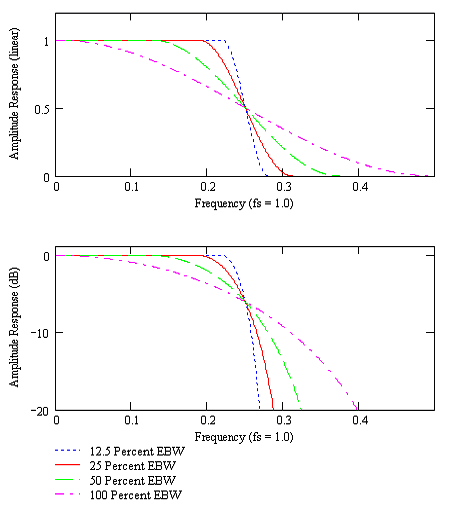 s is 1.0." align="middle" border="0">
Figure 5. These plots show the frequency response of Raised Cosine filters with 12.5, 25, 50, and 100 percent Excess Bandwidth (EBW). The responses shown are scaled for a system with two samples per symbol, so that the inflection point of the response is at f = 0.25 and the sample rate, fs is 1.0.
The pulse shapes associated with the Raised Cosine filter are shown in Figure 6. As EBW is reduced the main lobe widens and the sidelobe height increases.
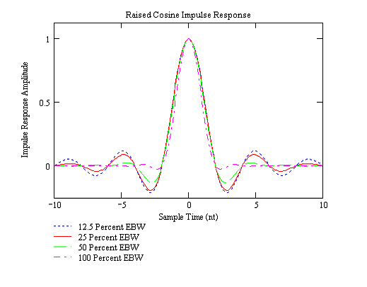
Figure 6. Shown are the time-domain impulse responses, or pulse shapes, for the Raised Cosine filters shown in Figure 5. The responses shown are for a 2x oversampled system so the common zero crossings occur at even-numbered samples, i.e., 2, 4, 6, etc. It can be seen that the symbol-spaced zero crossings are preserved for all EBWs so zero-ISI will be realized.
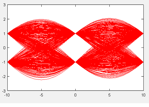
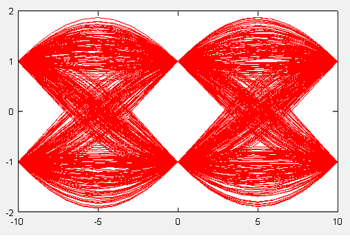
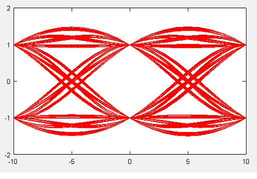
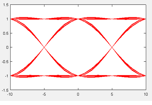
There are some tradeoffs associated with the choice of the percentage of EBW to use. The obvious characteristic of occupied bandwidth increases with EBW, so that systems that need to closely space carriers in order to maximize the number of channels in a band may benefit from low EBW filters. Unfortunately, low EBW also means an increase in Peak-to-Average-Power-Ratio (PAPR) as well as the length of the impulse response necessary to be computed in the digital processing without losing significant performance. Figures 7a-d show "eye diagrams" for the filters shown in Figures 5 and 6 using ten samples per symbol. This is the same as what would be seen with an oscilloscope triggered at a symbol boundary in an analog demodulator. The various traces are due to the different combinations of pulse summations for the bit patterns in the data stream.
The increase in PAPR can be observed in Figure 7 in the larger excursions of the signal traces for the low EBW cases compared to the higher EBW pulses. Table 1 contains the average power and PAPR levels for each case shown. It can also be observed that the "eye" stretches out and "opens" as EBW increases. One consequence of this is that systems using high EBW pulse shapes are less sensitive to jitter in the symbol recovery clock, since a deviation from the zero-ISI sampling point will generate a smaller potential error than it would with a low EBW pulse.
(a)
(b)
(c)
(d)
Figure 7. Shown are eye diagrams for a random binary stream modulated in BPSK with a Raised Cosine pulse with EBW of (a) 12.5%, (b) 25%, (c) 50%, and (d) 100%. The zero-ISI sampling point is easily seen at sample zero in each case, as well as at -10 and 10 for the adjacent symbols.
| EBW | Average Power (rms) |
PAPR (dB) |
| 12.5% | 0.98 | 3.4 |
| 25% | 0.97 | 2.9 |
| 50% | 0.94 | 2.0 |
| 100% | 0.87 | 0.9 |
Table 1. The Average Power and Peak-to-Average-Power-Ratios for the signals shown in Figure 7 are indicated. The average power is computed with the symbol magnitudes normalized to unity at the zero-ISI sample point. PAPR increases significantly as EBW is decreased while the average power remains relatively constant.
The mechanism by which the PAPR increases as EBW decreases can be seen in Figures 6 and 7. In Figure 6 it is evident that as EBW decreases the sidelobes increase in magnitude and the impulse response has significant energy further from the main lobe, i.e., the impulse response is effectively longer. It can be seen in Figure 7(a) that the peak trace arcs high between two symbols of the same value. Certain patterns, for example -1, 1, 1, -1, allow the sidelobes to add more constructively between symbols than others. When the sidelobes are high, as they are with a low EBW Raised Cosine pulse, the peaks caused by the constructive sidelobe addition are higher than they are for a pulse shape with low sidelobes. This can be seen as well with the 100% EBW trace in Figure 7(d), where the peak excursions are nearly non-existent compared to the symbol magnitude, and the impulse response as seen in Figure 6 has very low sidelobes.
It is also interesting to note that a continuum of Fourier Transform pairs exists between the symbol pulse shape and the frequency response of the system. As noted early on and shown in Figure 1, a rectangular pulse results in a sinx/x frequency response. This provides the shortest pulse in the time domain and the broadest spectral occupation. Likewise a long sinx/x pulse shape, for example the 12.5% EBW Raised Cosine, has the narrowest spectral occupation. It can be seen intuitively that as the frequency response approaches a brick-wall rectangular function the symbol pulse shape approaches a perfect sinx/x. The adjustability of the Raised Cosine pulse via the selection of the EBW percentage allows management of tradeoffs between spectral occupancy, PAPR, the length of the pulse shape, and the sensitivity to symbol clock jitter. This adjustability is one of the attractions of the Raised Cosine pulse shape, and many single-carrier air interface standards obtain interoperability at the pulse-matching level by specifying Raised Cosine system response with a specific EBW.
And that brings up the next important point which we have so far avoided. Should this pulse shaping be done in the transmitter or the receiver? The example of the transmitter with the rectangular pulses and a matching integrate-and-dump receive filter was discussed initially, but how should Raised Cosine pulses for zero-ISI be handled? The most common solution is to factor the frequency response into equal parts, i.e., use the square-root of the desired Raised Cosine system response in both the transmitter and the receiver. The resulting transmitted frequency response is commonly called a Root Raised Cosine (RRC) response. This means that the two sides of the link, the transmitter and receiver, are exactly matched to each other so that at the output of the pulse-shaping filter in the receiver (which realizes the aggregate RC frequency response) the symbols have zero-ISI and appear as shown in Figure 7.
Factoring the pulse shape to a square root response in each end of the link is a compromise that tries to balance a few common system constraints. As has been mentioned, the EBW parameter for the Raised Cosine pulse shape allows control of the occupied spectrum of a signal for the cases where spectrum is a valuable resource. Using a low EBW allows carriers to be placed closer together so that the number of channels can be maximized. An important aspect of this consideration is that the filter constrains the spectral sidelobes and out-of-band energy in order to minimize interference to adjacent channels. This suggests that the filtering in the transmitter needs to be good enough to provide such spectral shaping, and is a significant reason why rectangular transmit pulses are seldom used in practice.
So why not just put the entire Raised Cosine response in the transmitter rather than factoring it across both ends of the link? Putting the entire RC response in the transmitter means that the pulse has already been fully shaped by the time it gets to the receiver, so that any additional filtering will likely alter the response and potentially cause ISI. The best performance, that is, the lowest-ISI solution with an RC pulse fully shaped in the transmitter, is with no filtering at all in the receiver. This means that the receiver, including the synchronization and detection mechanisms, must deal with any adjacent channel energy and noise as well as the in-band signal energy and noise. This maximizes the noise level as well as interference sensitivity in the receiver, and increases the dynamic range handling requirement of the processing since the adjacent channel energy levels may be much higher than that of the desired signal. From this perspective the receive filter should be as tight around the transmitted spectrum as possible in order to reject as much noise and out-of-band interference as possible.
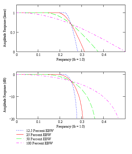
The common compromise, then, to simultaneously achieve tight control of the transmit spectrum as well as the receiver bandwidth and still have a zero-ISI response end-to-end, is to use Root Raised Cosine pulse shapes in both the transmitter and receiver. This also satisfies the usual signal processing maximum-likelihood detection constraint in that the filter in the receiver is matched, i.e., a matched filter, to the transmitted pulse shape. Figure 8 shows the frequency response of example Root Raised Cosine filters, which can be compared to the Raised Cosine filters in Figure 5. Figure 9 shows the time-domain impulse response for a Root Raised Cosine filter for the cases previously considered. It can be seen that the zero crossing points are no longer coincident, since ISI is not avoided until the pulse is again convolved with a matching filter. In other words, the autocorrelation function of a Root Raised Cosine impulse response will be zero at the symbol intervals, but the RRC impulse responses themselves will generally not be.
 s is 1.0." align="middle" border="0">
Figure 8. These plots show the frequency response of Root Raised Cosine filters with 12.5, 25, 50, and 100 percent Excess Bandwidth (EBW). The responses shown are scaled for a system with two samples per symbol, so that the inflection point of the response, which is also the 3dB point in an RRC filter, is at f = 0.25 and the sample rate, fs is 1.0.
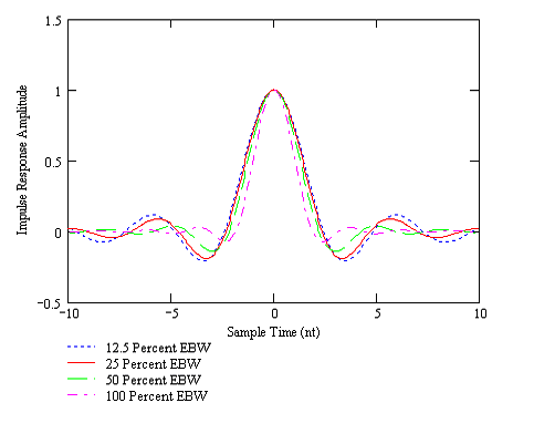
Figure 9. Shown are the time-domain impulse responses, or pulse shapes, for the Root Raised Cosine filters shown in Figure 8. These shapes correspond to the Raised Cosine pulses shown in Figure 6 in that the autocorrelation functions of the responses shown here result in the shapes shown in Figure 6.
It should be pointed out again for clarity and completeness that in a communication system any end-to-end response that provides zero-ISI at the symbol detector provides "matched filtering". It is not unusual for the filter impulse responses of the transmitter and receiver to not be identical. In one case where the age of the equipment on one end of the link created a situation where the transmit pulse filters were analog (i.e., a Butterworth filter) but the receive filters were digital, zero-ISI in the receiver was still achieved by creating a digital filter response that matched the transmit filter exactly. The zero-ISI constraint, as shown in Figure 4, is an end-to-end constraint realized at the output of the receiving pulse filter, and can therefore be managed by adjusting both the transmit and receive pulse filters, sometimes independently.There are a number of mathematical definitions and expressions for the Raised Cosine and Root Raised Cosine response. The differences are usually due to preferential variations with respect to trigonometric identities or managing variables, or perhaps just to be different. There’s a good, but not comprehensive, collection of definitions at
http://www.dspguru.com/info/faqs/rcform.htm
While many of the textbook definitions may look different from each other due to rearrangement of variables or trigonometric identities, in my experience they are generally equivalent.
Summary for Those Who Made It This Far
In digital, or discrete, communication systems a broad class of symbol pulse shapes is used in order to obtain a zero-ISI characteristic. One of the most common sub-classes of zero-ISI pulse shapes is the Raised Cosine response. A common implementation of the Raised Cosine involves factoring the response into two equal pulse-shaping filters that are used in both the transmitter and receiver; This factorization is done by taking the square root of the Raised Cosine frequency response and the resulting filter response bears the name "Root Raised Cosine" as a result. One advantage of the Raised Cosine approach is that it can be adjusted via selection of the "rolloff factor" or "Excess Bandwidth" in order to trade off various system design considerations.
References:
The following texts contain mathematical definitions for Raised Cosine responses:
[1] A. Bruce Carlson, Communication Systems, McGraw-Hill, 1968
[2] J.G. Proakis, Digital Communications, 4th Ed., McGraw-Hill, 2001
[3] E.A. Lee and D. G. Messerschmitt, Digital Communication, 2nd Ed., Kluwer Academic Publishers, 1994
[4] B. Sklar, Digital Communications, PTR Prentice Hall, 1988
Note: [3] includes a mathematical description of a time-domain RRC pulse shape.
Copyright © 2008, Eric Jacobsen, All Rights Reserved.
- Comments
- Write a Comment Select to add a comment


The following article might be of some help.
http://wirelesspi.com/computing-error-rates/
Qasim Chaudhari


Regards
ML
This job is highly appreciated. I have the same question which pulse shaping is used is IEEE 802.11a ,g and LTE standards which make the use of OFDM waveform

To post reply to a comment, click on the 'reply' button attached to each comment. To post a new comment (not a reply to a comment) check out the 'Write a Comment' tab at the top of the comments.
Please login (on the right) if you already have an account on this platform.
Otherwise, please use this form to register (free) an join one of the largest online community for Electrical/Embedded/DSP/FPGA/ML engineers:


