Setting Carrier to Noise Ratio in Simulations
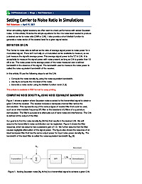
When simulating digital receivers, we often want to check performance with added Gaussian noise. In this article, I’ll derive the simple equations for the rms noise level needed to produce a desired carrier to noise ratio (CNR or...
Summary
This blog derives simple, practical equations to set the RMS Gaussian noise level required to produce a desired carrier-to-noise ratio (CNR) in digital receiver simulations. Readers will learn how to relate signal power, sample rate, and noise spectral density to discrete-time noise variance and how to handle real vs complex (baseband) signals when adding AWGN.
Key Takeaways
- Compute the RMS noise sigma from a target CNR and measured signal power (in linear or dB units).
- Convert between dB power, linear power, and RMS amplitude for both real and complex signals.
- Account for sample rate and equivalent noise bandwidth when translating noise spectral density (N0/2) to discrete-time variance.
- Apply correct AWGN generation methods for passband versus complex baseband simulations.
- Verify the implemented noise level by measuring CNR in the simulated time or frequency domain (FFT) and adjust for windowing effects.
Who Should Read This
Intermediate DSP or system simulation engineers (communications/radar focus) who build digital receiver simulations and need to set AWGN levels correctly to validate performance under specified CNR conditions.
TimelessIntermediate
Related Documents
- A New Approach to Linear Filtering and Prediction Problems TimelessAdvanced
- A Quadrature Signals Tutorial: Complex, But Not Complicated TimelessIntermediate
- An Introduction To Compressive Sampling TimelessIntermediate
- Lecture Notes on Elliptic Filter Design TimelessAdvanced
- Computing FFT Twiddle Factors TimelessAdvanced


