


Example Analog Filter
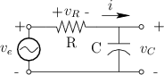
Figure E.1 shows a simple analog filter consisting of one resistor
(![]() Ohms) and one capacitor (
Ohms) and one capacitor (![]() Farads). The voltages across these
elements are
Farads). The voltages across these
elements are ![]() and
and ![]() , respectively, where
, respectively, where ![]() denotes
time in seconds. The filter input is the externally applied voltage
denotes
time in seconds. The filter input is the externally applied voltage
![]() , and the filter output is taken to be
, and the filter output is taken to be ![]() . By
Kirchoff's loop constraints [20], we have
. By
Kirchoff's loop constraints [20], we have
and the loop current is
Next Section:
Capacitors
Previous Section:
Laplace Analysis of Linear Systems


