


Feedback Comb Filters
The feedback comb filter uses feedback instead of a feedforward signal, as shown in Fig.2.24 (drawn in ``direct form 2'' [449]).
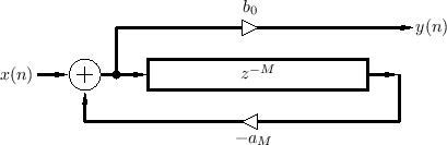
A difference equation describing the feedback comb filter can be written in ``direct form 1'' [449] as3.9
For stability, the feedback coefficient ![]() must be less than
must be less than
![]() in magnitude, i.e.,
in magnitude, i.e.,
![]() . Otherwise, if
. Otherwise, if
![]() ,
each echo will be louder than the previous echo, producing a
never-ending, growing series of echoes.
,
each echo will be louder than the previous echo, producing a
never-ending, growing series of echoes.
Sometimes the output signal is taken from the end of the delay line instead of the beginning, in which case the difference equation becomes
Next Section:
Feedforward Comb Filter Amplitude Response
Previous Section:
Feedforward Comb Filters


